DL205 Analog Manual, 7th Edition Rev. D
14-13
Chapter 14: F2-4AD2DA 4-Ch. In / 2-Ch. Out Analog Combination
1
2
3
4
5
6
7
8
9
10
11
12
13
14
A
B
C
D
1
2
3
4
5
6
7
8
9
10
11
12
13
14
A
b
C
D
Writing the Control Program
Before starting to write the program, some supplemental examples can be very helpful to the
programmer, such as:
• Input power failure detection
• Output data calculation
• Input data scaling
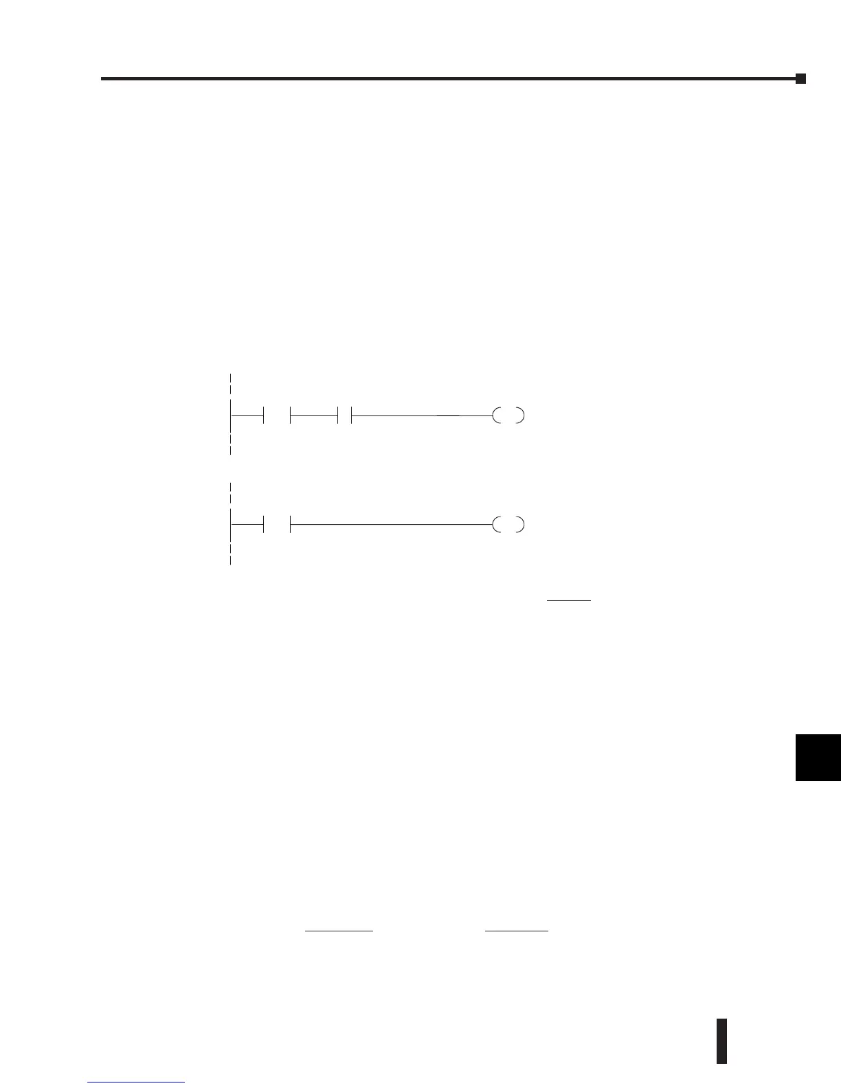
Analog Input Failure Detection
The analog module has a microcontroller that can diagnose analog input circuit problems.
Ladder logic can be written to detect these problems. The following rung shows an input
point that would be assigned if the module was used as shown in the previous and following
examples.
Calculating the Digital Value
The control program must calculate
the digital value that is sent to the
analog output. Several methods can be
used to do this, but the best method
is to convert the values to engineering
units. This is accomplished by using
the formula shown.
Adjustments may need to be made to
the formula depending on the scale of
the engineering units.
Consider the following example which controls pressure from 0.0–99.9 PSI. Using the
formula will calculate the digital value to be sent to the analog output. The example shows
the conversion required to yield 49.4 PSI. The multiplier of 10 is used because the decimal
portion of 49.4 cannot be loaded in the program, so it is shifted right one decimal place to
make a usable value of 494.
A = U
4095
H–L
A = Analog Value (0–4095)
U = Engineering Units
H = High limit of the engineering
unit range
L = Low limit of the engineering
unit range
V2000 K0
=
V-memory locationV2000 holds
channel1data.When a datavalue
of zero is returned and inputX37 is
on,thenthe analog channel is not
operating properly.
X37
OUT
C1
 Loading...

