DL205 Analog Manual, 7th Edition Rev. D
3-6
Chapter 3: F2-04AD-2 , F2-04AD-2L, 4-Channel Analog Voltage Input
1
2
3
4
5
6
7
8
9
10
11
12
13
14
A
B
C
D
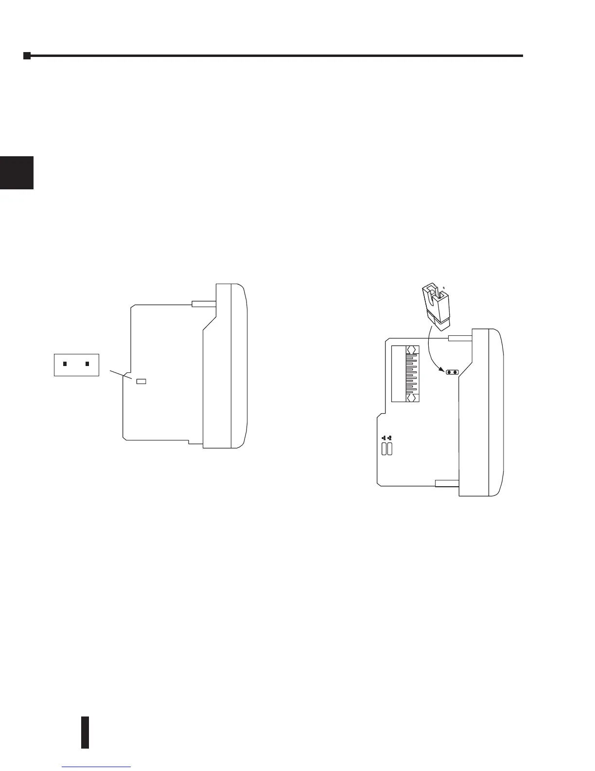
Selecting the Input Signal Range
There is another jumper, labeled either J2 or J3
that is used to select between the 5V ranges and
the 10V ranges (depending whether it is a single
or double circuit board module). See the figures
below to locate the jumper on the module being
used. The module comes from the factory set for
10V operation (jumper not installed).
1
2
3
4
5
6
7
8
9
10
11
12
13
14
A
b
C
D
J2
Install jumper J2 or J3 for
0–5V or W5V operation.
Remove J2 or J3, or store on
a single pin, for 0–10V or
W10V operation.
Jumper J2 is located on the smaller
circuit board, which is on top of the
motherboard.
Install J2 for 0–5V or W5V operation.
Remove J2, or store on a single pin, for
0–10V or W10V operation.
Jumper J2 location on modules having
Date Code 0609F4 and previous
(two circuit board design)
Jumper J3 location on modules having
Date Code 0709G and above
(single circuit board design)
J3
Install J3 for 0–5V or W5V
operation. Remove J3, or store on
a single pin, for 0–10V or W10V
operation.
 Loading...

