DL205 Analog Manual, 7th Edition Rev. D
6-8
Chapter 6: F2-04RTD 4-Channel RTD Input
1
2
3
4
5
6
7
8
9
10
11
12
13
14
A
b
C
D
Ambient Variations in Temperature
The F2-04RTD module has been designed to operate within the ambient temperature range
of 0°C–60°C.
Precision analog measurement with no long term temperature drift is assured by a chopper
stabilized programmable gain amplifier, ratiometric referencing, and automatic offset and gain
calibration.
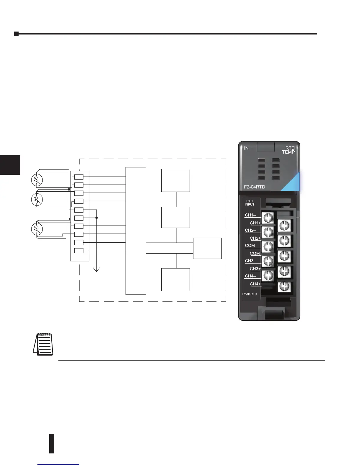
Wiring Diagram
The F2-04RTD has a terminal block which simplifies wiring and can be removed to make
removal of the module possible without disturbing field wiring.
NOTE 1: The three wires connecting an RTD to the module must be the same type and length. Do not use the shield or
drain wire for the third connection.
NOTE 2: If an RTD sensor has four wires, the plus (+) sense wire should be left unconnected as shown.
1
2
3
4
5
6
7
8
9
10
11
12
13
14
A
b
C
D
A/D
+
-
Ch1
Ch2
Ch3 --
Ch4 --
Ch1
+
Ch2
+
Ch3 +
Ch4 +
C
C
200 A
Current
Source
200 A
Current
Source
Ref.
Adj.
x
Note 2
Note 1
-
-
0V
Analog Multiplexer
CH1+
CH2+
COM
CH3+
CH4+
CH1–
CH2–
COM
CH3–
CH4–
F2-04RTD
IN RTD
TEMP
RTD
INPUT
F2-04RTD
 Loading...

