DL205 Analog Manual, 7th Edition Rev. D
2-16
Chapter 2: F2-04AD-1, F2-04AD-1L, 4-Channel Analog Current Input
1
2
3
4
5
6
7
8
9
10
11
12
13
14
A
B
C
D
Reading Values (Multiplexing) for the DL230, DL240, DL250-1 and DL260
The DL230 CPU does not have the special V-memory locations which will allow data transfer
to be automatically enabled. Since all channels are multiplexed into a single data word, the
control program must be setup to determine which channel is being read. Since the module
appears as X input points to the CPU, it is very easy to use the active channel status bits to
determine which channel is being monitored.
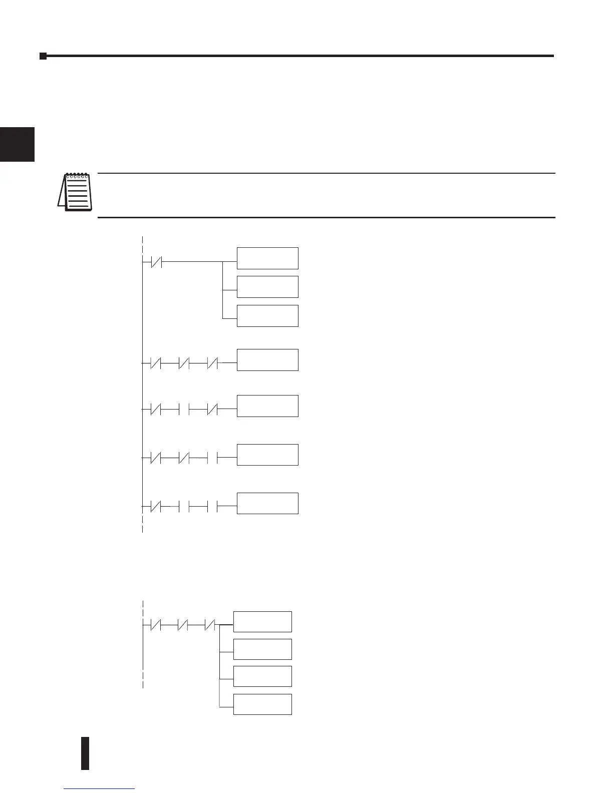
NOTE: This example is for a module installed as shown in the previous examples. The addresses used would be different
if the module was installed in a different I/O arrangement. The rungs can be placed anywhere in the program, or if stage
programming is being used, place them in a stage that is always active.
Single Channel Selected
Since it isn’t necessary to know which channel is selected, the single channel program is even
more simple as shown in the example below.
1
2
3
4
5
6
7
8
9
10
11
12
13
14
A
b
C
D
It is usually easier to perform math operationsinBCD,
so it is besttoconvert the datatoBCD immediately.
Youcan leave out this instruction if your application
does notrequire it.
This instruction masksthe channelidentification bits.
Without this,the values used will not be correctsodo
not forget to include it.
Loadsthe complete datawordintothe accumulator.
TheV-memorylocation depends on theI/O
configuration.See Appendix Afor thememorymap.
LD
V40401
ANDD
KFFF
BCD
OUT
V2000
When themoduleis not busyand X34 and X35are
off, channel1dataisstoredinV2000.
X36 X34 X35
It is usually easierto perform math operationsin
BCD, so it is best to convertthe datatoBCD
immediately.You canleave out this instructionifyou
applicationdoesnot requireit.
This instructionmasks thechannel identification
bits.Without this,the values used will not be correct
so do notforget to includeit.
Loads thecompletedatawordintothe accumulator.
TheV-memorylocation depends on theI/O
configuration. SeeAppendix Afor the memory map.
LD
V40401
ANDD
KFFF
BCD
X36
X36 X34 X35
StoreChannel1
OUT
V2000
When themodule is not busy andX34 and X35are
off, channel1dataisstoredinV2000.
When X34ison and X35isoff,channel 2datais
stored in V2001.
When X34isoff andX35 is on, channel 3dat ais
stored in V2002.
When both X34 and X35are on, channel 4datais
stored in V2003.
X36 X34 X35
StoreChannel2
OUT
V2001
X36 X34 X35
StoreChannel3
OUT
V2002
X36 X34 X35
StoreChannel4
OUT
V2003
 Loading...

