DL205 Analog Manual, 7th Edition Rev. D
9-17
Chapter 9: F2-02DA-2, F2-02DA-2L, 2-Channel Analog Voltage Output
1
2
3
4
5
6
7
8
9
10
11
12
13
14
A
B
C
D
Negative Values with Bipolar Range
If the bipolar ranges (±5V, ±10V) are used or an output data format of ±2047, the data value
needs to be specified whether it is positive or negative. There are two ways to show that the
value is negative:
• Turn on the sign output (Y37 in the examples, DL230 only).
• Embed the sign output in the data value (required for the DL240/250-1/260 using the pointer
method, an optional method for the DL230).
To embed the sign output in the data values, OR 8000 to the value. This has the same effect
as turning on Y37. Remember, the V-memory location is mapped directly to the outputs.
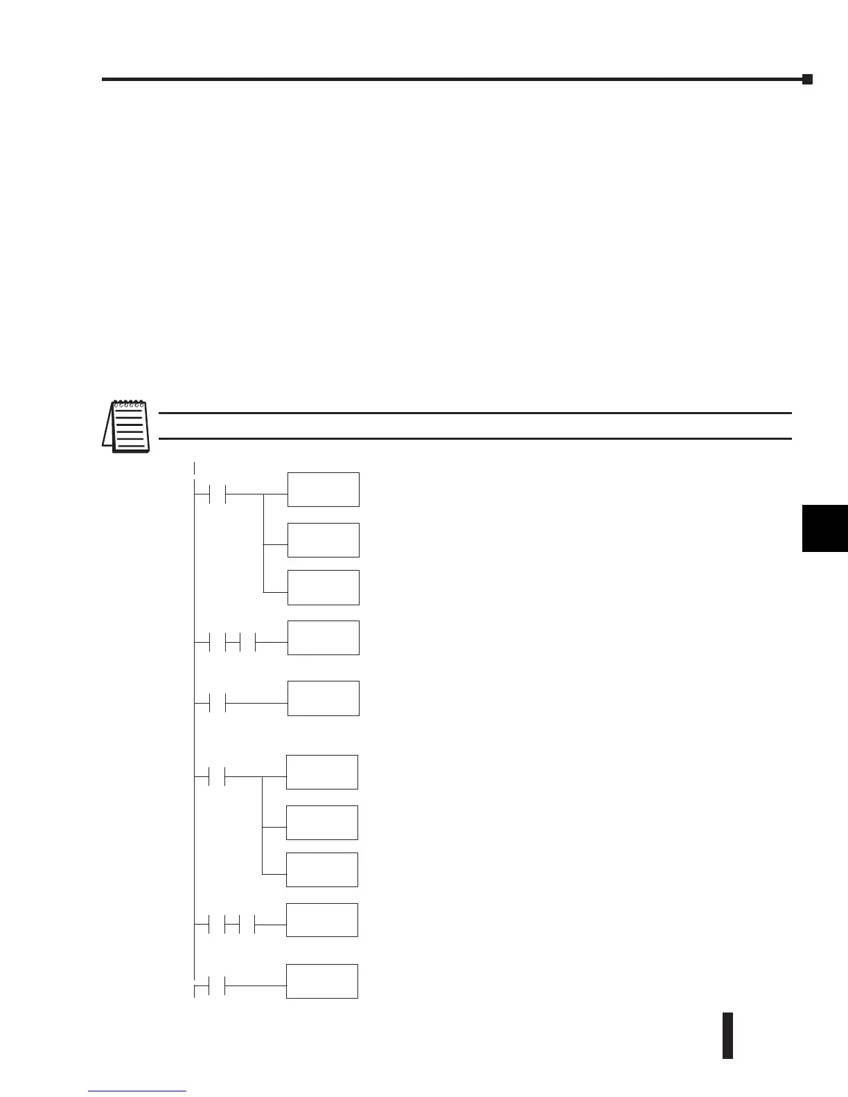
If bipolar ranges are used, logic needs to be added to indicate either positive or negative values.
The logic would be similar for both values, but some type of permissive contact needs to be
used to select the appropriate section of logic. Following is an example that re-scales a variable
from a 0–1000 range to a 0–2047 range. It includes a step that combines 8000 with the value
to make it negative.
NOTE: Do not exceed a value of 2047 for ±2047 output formats.
1
2
3
4
5
6
7
8
9
10
11
12
13
14
A
b
C
D
TheLDinstruction loads the engineering unitsusedwithChannel1into
theaccumulator.This exampleassumesthe numbers areBCD.Since
X0 is used, this rung only executes when X0 is on (X1 would be the
inputthat wouldindicate a negativevalue should be used).
LD
V2300
X0
MUL
K2047
DIV
K1000
Multiply theaccumulator by 2047 (tostart theconversion).
Divide theaccumulator by 1000 (becauseweusedamultiplierof 10,
we have to use 1000 instead of 100).
OUT
V2000
Storethe result in V2000.This is thedigital value, in BCDform, that
should be sent to themodule(theactualsteps required to send the
data areshownlater).
ORD
K8000
This ORDinstruction imbedsthe sign output in thedatavalue when
X0 and X1 areon. It combines theBCD value(8000) with the
accumulator valuetomakeit negative.Omitthis rung if youchoose
to controlthe sign bitofthe module (Y37) directly.
X0 X1
X0
TheLDinstruction loadsthe engineering units used with Channel2
intothe accumulator. This example assumesthe numbers areBCD.
SinceX0isused, this rung only executes when X0 is on (X2 wouldbe
theinput that wouldindicateanegative value should be used).
LD
V2301
X0
MUL
K2047
DIV
K1000
Multiply theaccumulator by 2047(to startthe conversion).
Divide theaccumulator by 1000(becauseweusedamultiplierof10,
we have to use 1000instead of 100).
OUT
V2001
Storethe result in V2001. This is thedigital value, in BCDform, that
should be sent to themodule (the actual steps required to send the
 Loading...

