DL205 Analog Manual, 7th Edition Rev. D
15-11
Chapter 15: F2-8AD4DA-1 8-Ch. In / 4-Ch. Out Analog Current Combination
1
2
3
4
5
6
7
8
9
10
11
12
13
14
15
B
C
D
1
2
3
4
5
6
7
8
9
10
11
12
13
14
15
b
C
D
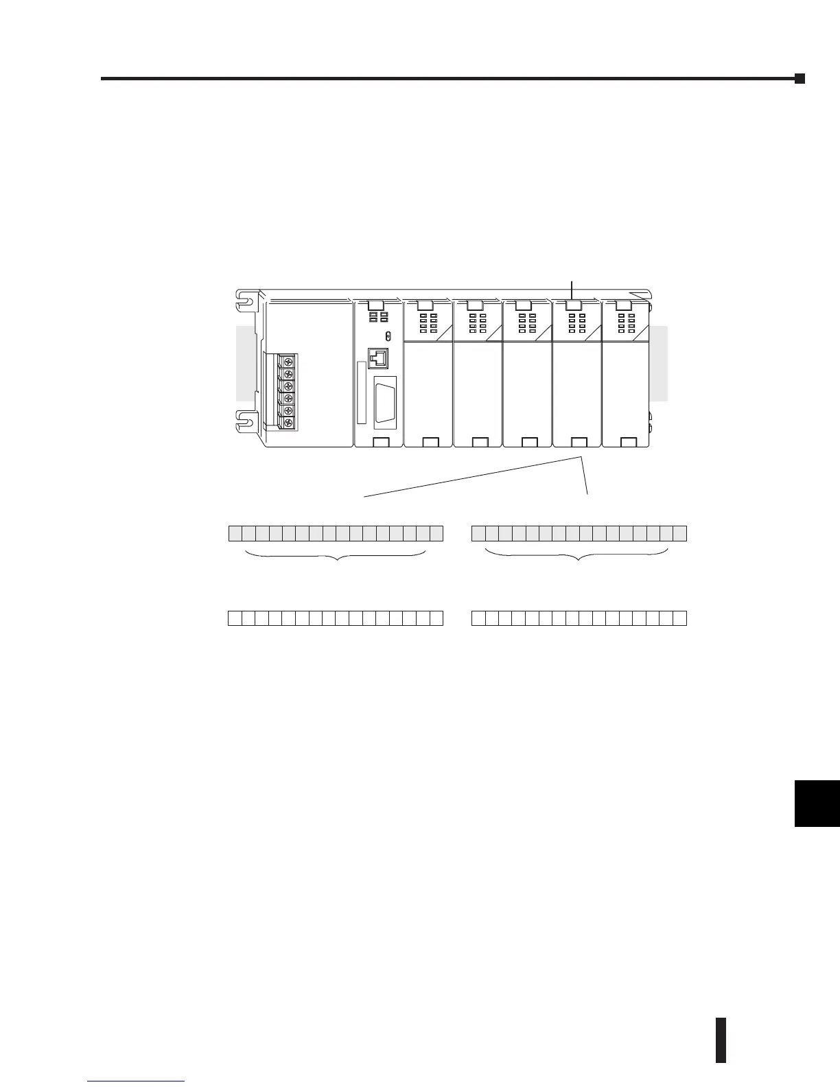
Understanding the I/O Assignments
The F2-8AD4DA-1 module appears to the CPU as having 32 discrete input and 32 discrete
output points. These points provide the data value, channel identification and settings for
resolution, range, and track and hold feature. These bits may never have to be used, but it may
be an aid to help understand the data format.
Since all output points are automatically mapped to V-memory, the location of the data words
that will be assigned to the module can simply be determined.
The individual bits in these data word locations represent specific information about the
analog signal. (The specific memory locations may vary, depending upon the slot where the
F2-8AD4DA-1 module is located.)
Y
3
7
BSLBSM
Y
2
0
Output Data Bits
F2-8AD4DA-- 1
V40501
V40500 V40503
8pt
Input
8pt
Input
32pt In
32pt OutOutput
8pt
16pt
Output
X0
--
X7
X10
--
X17
Y0
--
Y17
Y20
--
Y57
Y60
--
Y67
Slot 0Slot1 Slot 2Slot 3Slot 4
V40400
X20
--
X57
V40401
X
2
0
InputDataBits
X
3
7
BSLBSM
Y
5
7
BSLBSM
Y
4
0
V40502V40402
X
4
0
X
5
7
BSLBSM
 Loading...

