DL205 Analog Manual, 7th Edition Rev. D
5-16
Chapter 5: F2-08AD-2, 8-Ch. Analog Voltage Input
1
2
3
4
5
6
7
8
9
10
11
12
13
14
A
B
C
D
Using Bipolar Ranges (Pointer Method) for the DL240, DL250-1
and DL260 CPUs
Some additional logic is needed with bipolar ranges to determine whether the value being
returned represents a positive voltage or a negative voltage. For example, the direction of a
motor may be needed to be known. With the DL240/250 CPU, the last input cannot be
used to show the sign for each channel (X37 in the previous examples). This is because the
DL240/250-1/260 reads all eight channels in one scan. Therefore, if X37 were used, the last
channel read would just be monitored and the sign would not be able to be determined for the
previous channels. A simple solution is if the value read is greater than or equal to 8001 the
value is negative.
The sign bit is the most significant bit, which combines 8000 with the data value. If the value
is greater than or equal to 8001, only the most significant bit and the active channel bits will
need to be masked to determine the actual data value.
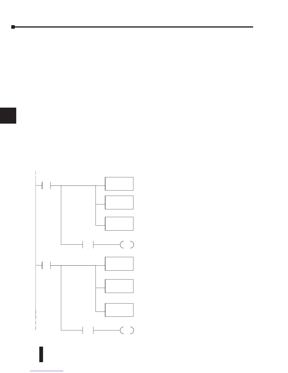
The following program shows how to accomplish this. Since a negative value is always meant
to be known, these rungs should be placed before any other operations that use the data, such
as math instructions, scaling operations, and so forth. Also, if stage programming instructions
are being used, place these rungs in a stage that is always active. Please note, this logic is only
needed for each channel that is using bipolar input signals. The following example only shows
two channels.
1
2
3
4
5
6
7
8
9
10
11
12
13
14
A
b
C
D
SP1
OUT
C1
LD
V2000
OUT
V2020
Load channel 1datafromV-memoryintothe
accumulator. Remember,the data canbe negative.
Contact SP1 is always on.
Putthe actual signal value in V2020. Nowyou canuse
thedatanormally.
ANDD
K7FFF
This instruction masks thesignbit of theBCD dataifit
is set. Withoutthis step, negative values will not be
correct,sodo not forget to include it.
V2000 K8001
Check Channel2
Channel 1datais negativewhenC1ison(avalue of -- 1
reads as 8001 ,--2 is 8002, etc.).
SP1
OUT
C2
LD
V2001
OUT
V2021
Load channel 2fromV-memoryintothe accumulator.
Remember, the datacan be negative.Contact SP1 is
always on.
Putthe actual signal value in V2021. Nowyou canuse
thedatanormally.
ANDD
K7FFF
This instruction masks thesignbit of theBCD data, if it
is set. Withoutthis step, negative values will not be
correct,sodo not forget to include it.
V2001 K8001
Channel 2datais negativewhenC2ison(avalue of -- 1
reads as 8001 ,--2 is 8002, etc.).
²
²
 Loading...

