DL205 Analog Manual, 7th Edition Rev. D
5-19
Chapter 5: F2-08AD-2, 8-Ch. Analog Voltage Input
1
2
3
4
5
6
7
8
9
10
11
12
13
14
A
B
C
D
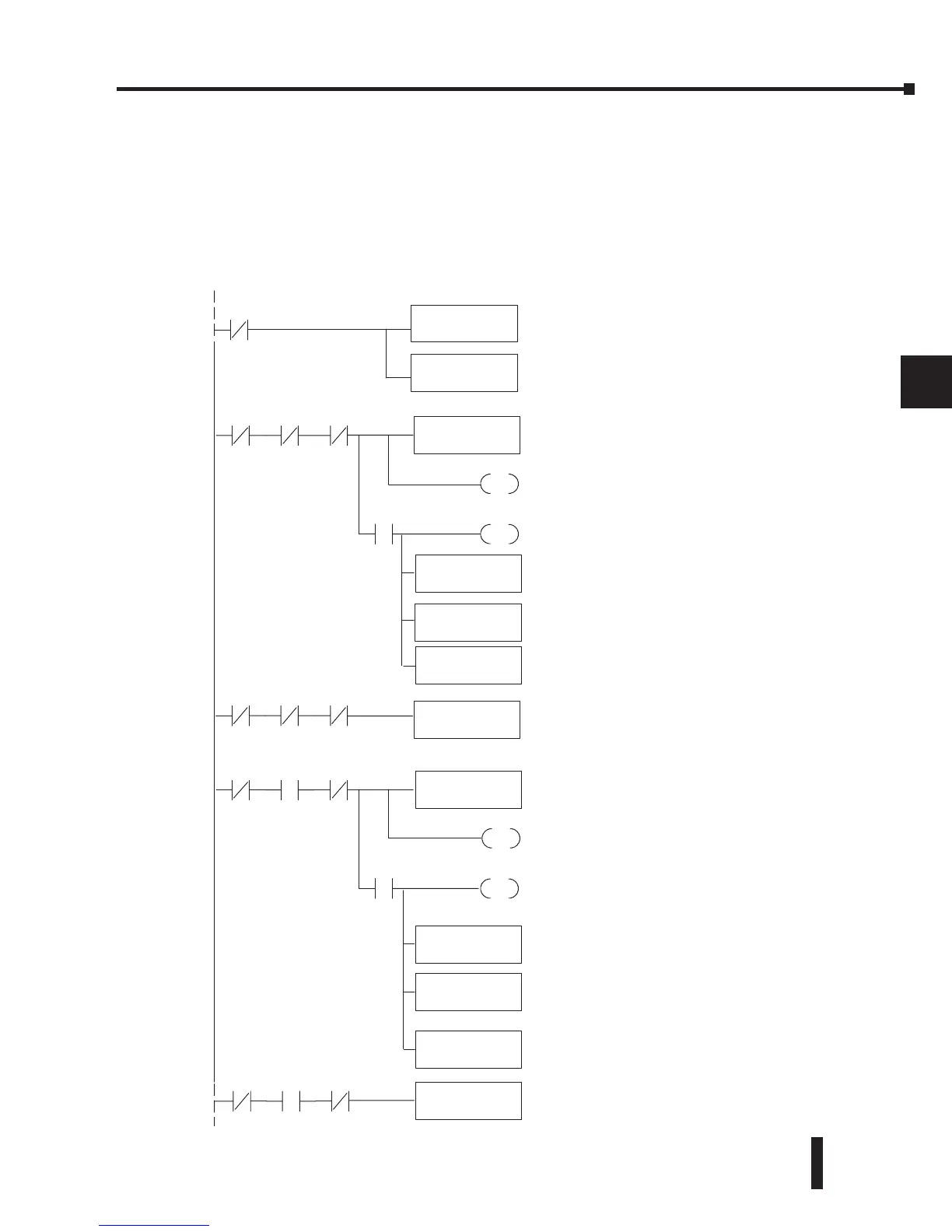
Using 2’s Complement for the DL230, DL240, DL250-1, and the DL260 CPUs
(Multiplexing)
The 2’s complement data format may be required to display negative values on some operator
interface devices. It could also be used to simplify data averaging on bipolar signals.
The example shows two channels, but these steps can be repeated for all eight channels if
necessary.
1
2
3
4
5
6
7
8
9
10
11
12
13
14
A
b
C
D
This instructionmasks thechannelidentification bits
Without this,the values used will notbecorrect,so
do not forget to include it.
Loadsthe complete datawordintothe accumulator.
TheV-memorylocation dependsonthe I/O
configuration.See Appendix Afor thememorymap.
Loaddatawhenmoduleisnot busy.
LD
V40401
ANDD
KFFF
X36
X36 X34 X35
StoreChannel 1
OUT
V2000
When themoduleis not busy, and X34, X35 and
X36are off, channel1dataisstoredinV2000.C0
is resettoindicate that channel 1’svalue is positive.
SET
C0
X37
RST
C0
If X37ison, then the datavalue representsa
negative voltage. C0 is settoindicatethat
channel1’s value is negative.
X36 X34 X35
StoreChannel 2
OUT
V2001
When themoduleis not busy, and X34ison and
X35and X36are off, channel 2dataisstoredin
V2001.C1isreset to indi cate that channel2’s
value is positive.
SET
C1
X37
RST
C1
If X37ison, then thedatavalue representsa
negative voltage. C1 is settoindicate that
channel2’s value is negative.
INV
ADDD
K1
OUTD
V2040
INV
ADDD
K1
OUT
V2042
X36 X34 X35
X36 X34 X35
Invert thebit pattern in theaccumulator.
Invert thebit pattern in theaccumulator.
BCD
Channel1dataisindoublewordstarting at V2040.
BCD
Channel2dataisindoublewordstarting at V2042.
 Loading...

