DL205 Analog Manual, 7th Edition Rev. D
9-21
Chapter 9: F2-02DA-2, F2-02DA-2L, 2-Channel Analog Voltage Output
1
2
3
4
5
6
7
8
9
10
11
12
13
14
A
B
C
D
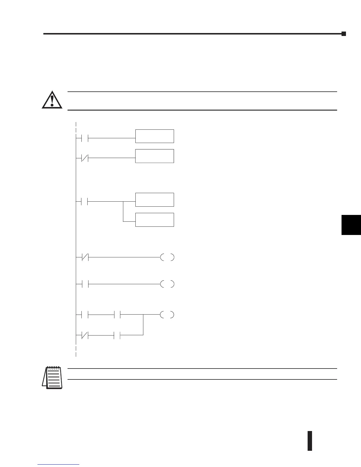
If the output range format of ±2047 is used (also most commonly used with bipolar voltage
ranges), the data values must be specified as either positive or negative. The previous example
could be used with an addition to activate the sign output bit, or use the following example
which uses individual contacts to determine the sign bit status for each channel.
WARNING: DO NOT USE THIS METHOD if the sign information is embedded into the data value by adding
8000 to it. Use the previous example.
NOTE: Do not exceed a value of 2047 for ±2047 output data formats.
1
2
3
4
5
6
7
8
9
10
11
12
13
14
A
b
C
D
Loads the datafor channel1intothe accumulator.
Loaddataintothe accumulator.
SP7
SP1
Send data to V-memory assigned to themodule.
BIN
Convertthe datatobinary(youmustomitthis step if
you haveconvertedthe datatobinary).
SP1 is always on.
OUT
V40501
LD
V2000
SP7
LD
V2001
Loads the datafor channel2intothe accumulator.
TheOUT instruction sendsthe data to themodule. Our
examplestartswithV40501, but theactual value
dependsonthe locationofthe moduleinyour
application.
OUT
Y37
SP7
Select thechannelto update.
Selectschannel1for updatewhen Y34isOFF
(Y35--ON deselects channel 2).Note, Y34and Y35are
used duetothe previous examples.Ifthe module was
installedinadifferent I/Oarrangement, theaddresses
wouldbedifferent.
Selectschannel2for updatewhen Y35isOFF
(Y34--ON deselects channel 1).Note, Y34and Y35are
used duetothe previous examples.Ifthe module was
installedinadifferent I/Oarrangement, theaddresses
wouldbedifferent.
X2
Thepermissive X1 activatesY37 (sign bit) during a
channel1update scan. The permissive X2 activates
Y37 duringachannel2update scan. Thesignbit (Y37
ON)indicatesthatthe value is negative. Youcould use
another permissive,suchasaCR,etc.
X1
OUT
Y34
SP7
OUT
Y35
SP7
SP7
 Loading...

