DL205 Analog Manual, 7th Edition Rev. D
16-14
Chapter 16: F2-8AD4DA-2, 8-Ch. In / 4-Ch. Out Analog Voltage Combination
1
2
3
4
5
6
7
8
9
10
11
12
13
14
15
16
C
D
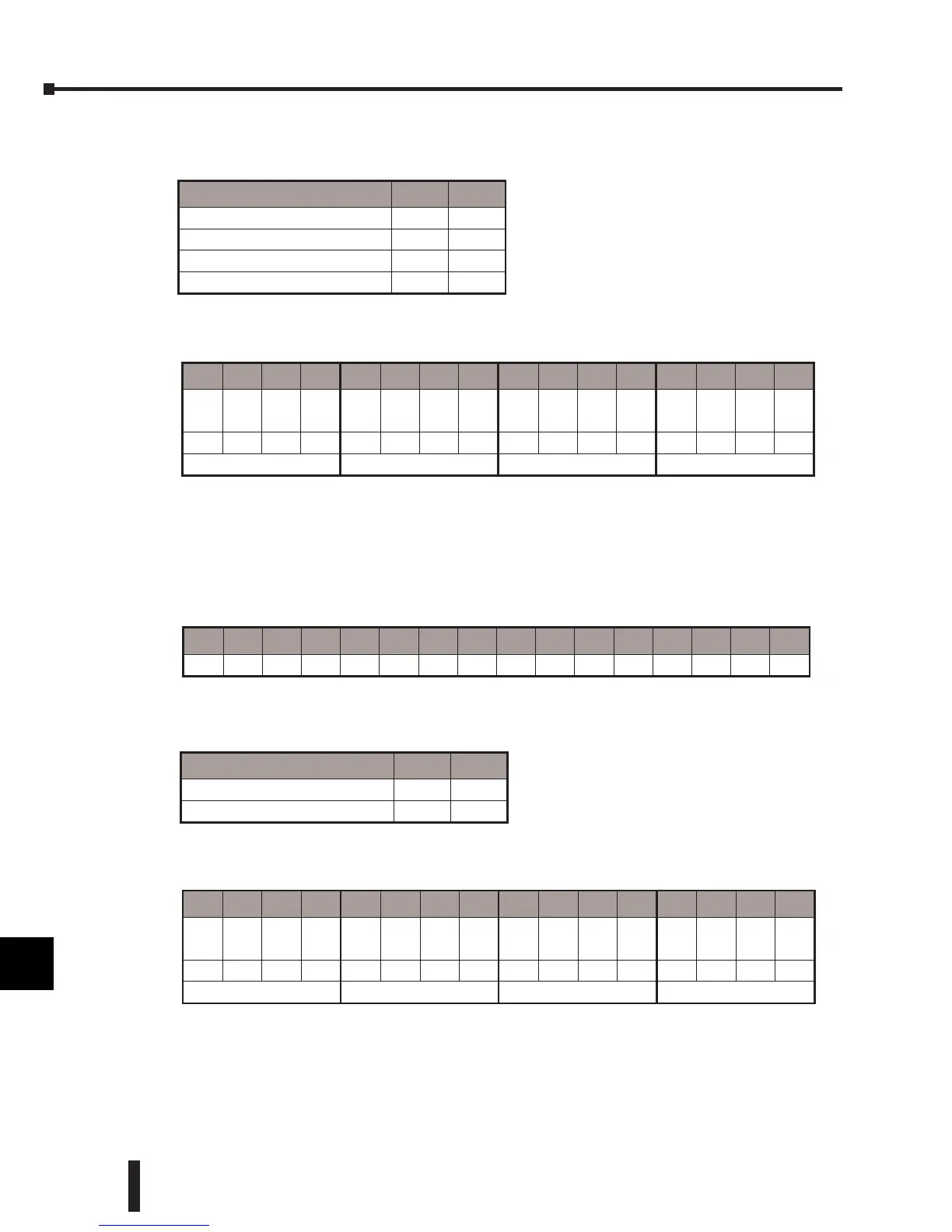
RnH = Resolution channel n High bit
RnL = Resolution channel n Low bit
Example: Input channels 1–4 are 12 bit, channel 5 is 14 bit, and channel 6 is 16 bit, and
channels 7 and 8 are disabled; V36403-F900(hex).
Input and Output Range Selection Bits
The range of the eight input channels can be collectively set for 0–5V or for 0–10V. The range
of the four output channels can also be collectively set for either of the same two voltage ranges.
V36413: (specific memory location will vary depending upon the base and slot location).
IR =
Input Range
OR = Output Range
Example: Input channel range is 0–5V, and output channel range is 0–10V;
V36413=100(hex).
1
2
3
4
5
6
7
8
9
10
11
12
13
14
15
16
C
D
Input Resolution Select RnH RnL
12 bit 0 0
14 bit 0 1
16 bit 1 0
Disabled 1 1
15 14 13 12 11 10 9 8 7 6 5 4 3 2 1 0
R-
8H
R-
8L
R-
7H
R-
7L
R-
6H
R-
6L
R-
5H
R-
5L
R-
4H
R-
4L
R-
3H
R-
3L
R-
2H
R-
2L
R-
1H
R-
1L
1 1 1 1 1 0 0 1 0 0 0 0 0 0 0 0
F 9 0 0
15 14 13 12 11 10 9 8 7 6 5 4 3 2 1 0
– – – – – – – OR – – – – – – – IR
Input/Output Range IR OR
0–5V 0 0
0–10V 1 1
15 14 13 12 11 10 9 8 7 6 5 4 3 2 1 0
– – – – – – – OR – – – – – – – IR
0 0 0 0 0 0 0 1 0 0 0 0 0 0 0 0
0 1 0 0
 Loading...

