DL205 Analog Manual, 7th Edition Rev. D
16-27
Chapter 16: F2-8AD4DA-2, 8-Ch. In / 4-Ch. Out Analog Voltage Combination
1
2
3
4
5
6
7
8
9
10
11
12
13
14
15
16
C
D
Calculating the Digital Output Value
The value sent to the 16 bit analog output
module must be in digital form. A very good
method to do this is to convert the value into
engineering units. Use the formula shown on
the right to accomplish this.
Adjustments to the formula may be needed
depending on the scale chosen for the engi-
neering units.
Consider the following example which controls
pressure from 0.0–140.0 PSI. By using the formula, the digital value can be determined that
can be sent to the module. The example shows the conversion required to yield 52.5 PSI.
Notice the formula divides by 10, because the BCD representation of 52.5 includes a multi-
plier of 10 to allow for the implied decimal. The division corrects for the multiplier.
Calculating Output Data: Engineering Units Conversion
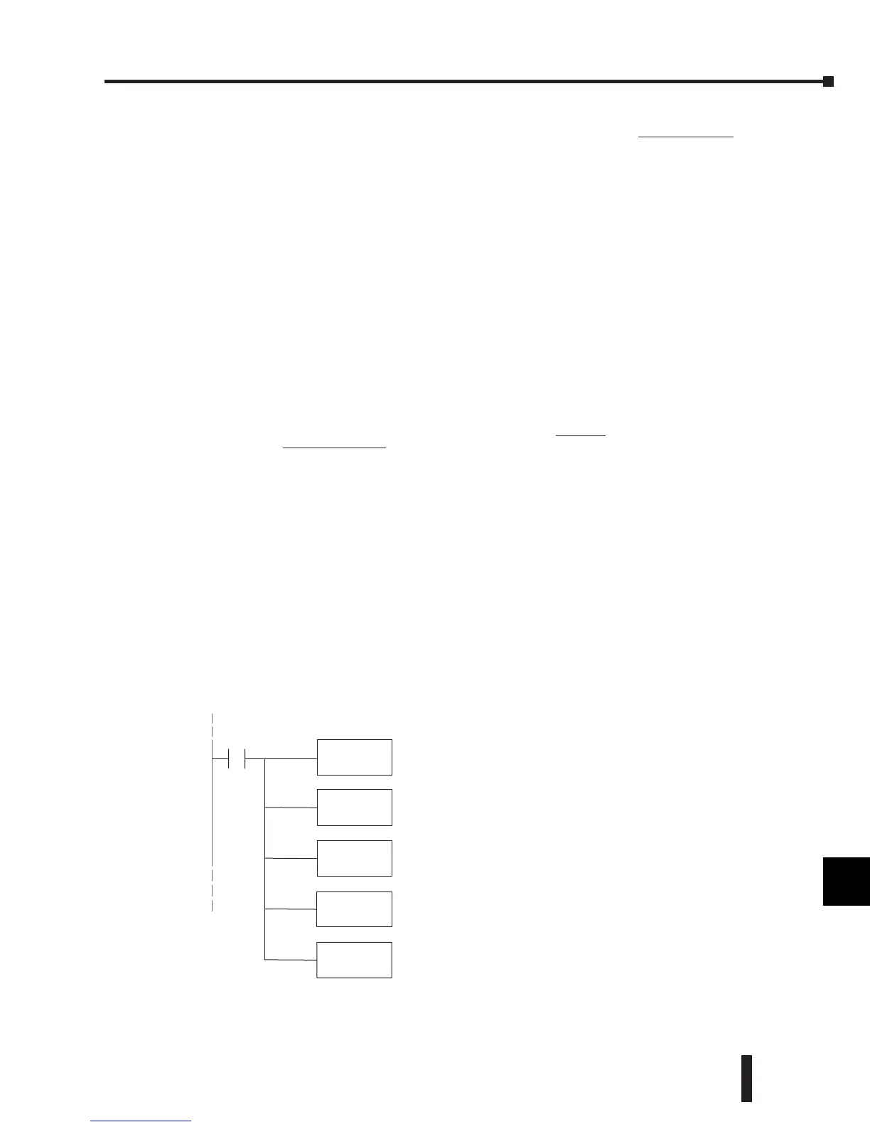
The below example program shows how to write the program to perform the engineering
unit conversion to output the 16 bit data format of 0–65535. This example assumes that
the engineering units have been calculated or loaded, including a multiplier of 10, in BCD
format and stored it in V2120 for output channel 1.
Output Engineering Unit Conversion / Output Data Calculation Example:
Data format = binary,
Channel 1 data memory location = V2020,
Channel 1 engineering units = 0.0–140.0 PSI,
1
2
3
4
5
6
7
8
9
10
11
12
13
14
15
16
C
D
D = EU
D
max
(EU
H
– EU
L
)
D = digital value
EU = engineering units
EU
H
= engineering unit range
high limit
EU
L
= engineering unit range
low limit
D = 10EU
D
max
10(EU
H
– EU
L
)
D = 525
65535
D = 24576
10(140)
BIN
ConvertfromBCD to binary dataformat.
MULB
KFFFF
Multiply by 65535;
FFFF hex =65535;
16 bit maximumdigital value.
DIVB
K578
Divide by 1400;
578 hex = 1400;
EU range X10for implieddecimal.
LD
V2120
SP1
Loadoutput channel datavalue into accumulator;
BCDEUvalue X10for implied decimal.
OUT
V2020
Storeoutput digitalvalue in V2020.
 Loading...

