Uni-Probe LB 490
BERTHOLD TECHNOLOGIES GmbH & Co. KG
2 – 149
Volume 2 2 Installation
2
For details on how to position the collimator please see the techni-
cal drawing in section 6.2.4 on page 2–258.
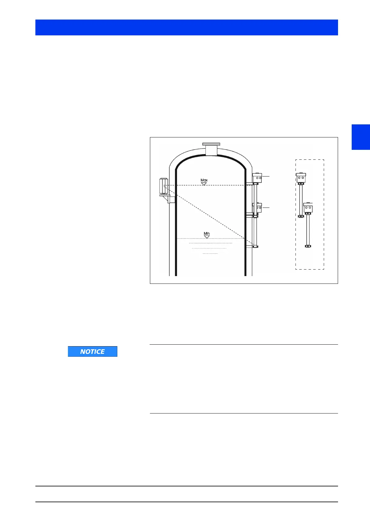
Multi-detector arrangement
Several detectors are necessary to cover detector lengths of more
than 2m (alternative: Tower-Sens). The detectors are arranged
such that the sensitive areas of the detector overlap seamlessly.
The detectors are slightly offset on the side (Figure 2-4). The sen-
sitive areas are marked by grooves, see also Figure 2-27.
Figure 2-4 Multi-detector arrangement
For installation details see the technical drawing in chapters 6.2.11
and 6.2.12 on page 2–263.
2.4.2 Tower-Se ns
Function failure due to damaged detector
The detector fixture must not transfer any vibrations or heat onto
the detector; otherwise the detector will be disturbed or may fail
altogether.
Therefore, install the fixture on a vibration-free support or attenu-
ate possible vibrations using vibration absorbers. Make sure to pre-
vent heat transfer to the detector via the detector fixture by using
suitable insulating materials.
The Tower-Sens detector supports a detector length of up to 8m. If
needed, the Tower-Sens can be extended in several parts. The
basic module for the Tower-Sens detector is always arranged at the
Main Unit
Auxiliary
Unit
Side view
 Loading...
