Chapter 4: Installation and Setup
Installation Steps
4-18 011-003-991 EN
1. Lift the actuator from the box. Carefully lay the assembly on its right side (NOT on the side with the
linear encoder).
The actuator support bolts for the 2000-Series actuators are metric, M10 x 1.5 thread pitch,
25mm long. The support pin and mounting bolts must not extend more than 0.40 in (10 mm)
into the actuator, otherwise, binding or damage to the carriage may occur.
DO NOT use 900-Series M10 x 1.25 mounting bolts. They have a different thread pitch and
will not interchange with those used on the 2000-Series.
2. Use of a guide pin is suggested. It is not provided with the actuator. If you require a guide pin, use
a solid metal dowel pin, 12mm diameter, which must not extend into the actuator more than 0.40
inch (10mm) from your support.
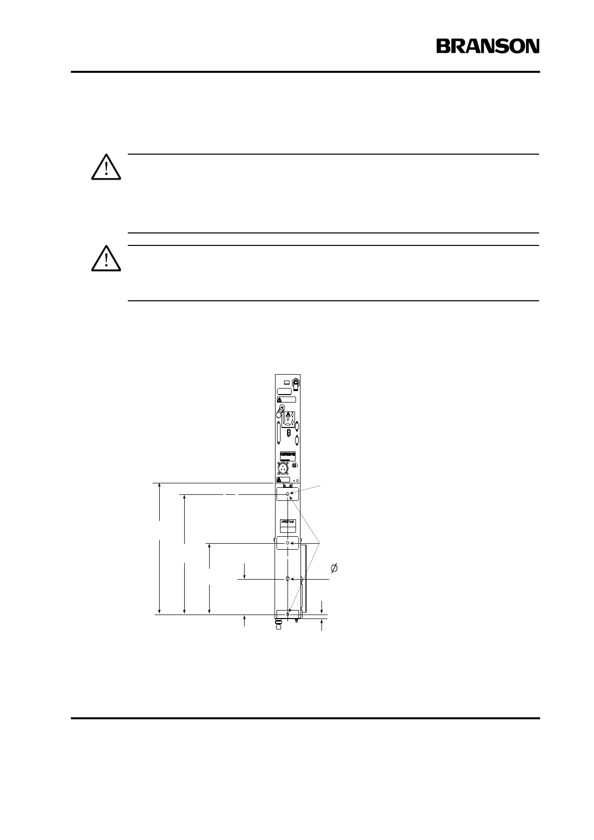
Figure 4.8 Actuator Rear View, Mounting Surface, Bolt and Guide Pin Locations
For 12 mm
Dowel Pin
.477
M10 x 1.5 THDS
10 mm deep
(3 places)
4.25
108 mm
8.50
216 mm
14.30
363 mm
15.63
397 mm
50
13 mm
Machined mounting
surfaces (3 places)**
Rear view of ae/aed actuator is shown. Although
other actuators will vary in height, referenced
dimensions will be the same for all models.
**These three mounting surfaces are flat
within 0.004 in. (0.1mm) TIR, in a tolerance
zone of 16 x 3.5 in. (410 x 90 mm). The
surface to which the actuator is mounted
must also have the same flatness tolerance.