Chapter 4: Installation and Setup
Start Switch Connection (Automation)
4-30 011-003-991 EN
Refer to the Branson Automation Guide (EDP 100-214-273) for additional information about
selection and use of Input and Output features listed in the following Table.
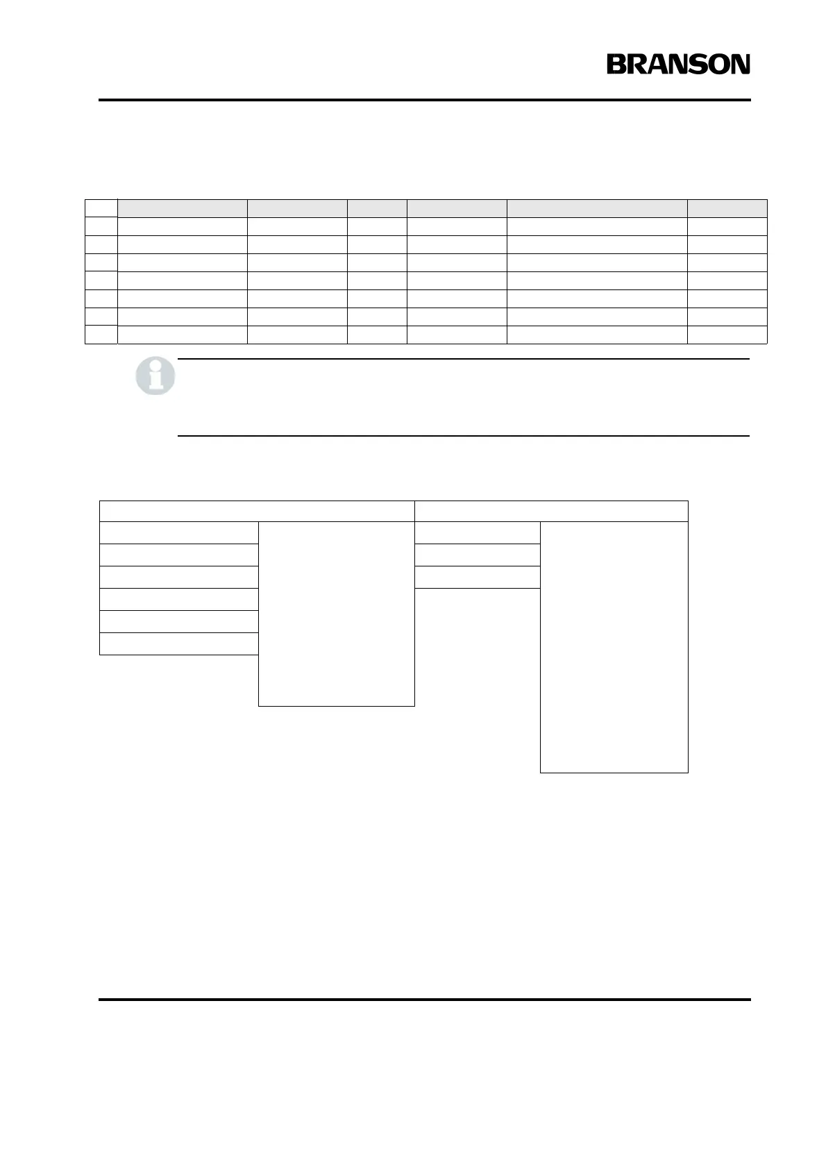
Table 4.7 User I/O Input and Output Function Selection
* This option is not available at J3-1 Input.
4.6.4 Input Power Plug
If you must add or change the input power plug, use the following color code for the conductors found in the
international harmonized line cord. Add the plug that is appropriate for your input power receptacle.
Pin Signal Name Signal Type Direction Signal Range Definition Colors
23 +10V_REF Analog Output 10.0V 10VDC ref. voltage from PS Wht/Red/Grn
12 24V_RTN 24V Ground Input 0V 24V Return Orn/Red
13 24V_SRC 24V Source Output 24V, 1.25A max 24V Source Blu/Red
27 24V_RTN 24V Ground Input 0V 24V Return Blu/Wht/Orn
28 24V_SRC 24V Source Output 24V, 1.25A max 24V Source Blk/Wht/Orn
41 24V_RTN 24V Ground Input 0V 24V Return Grn/Orn/Red
42 24V_SRC 24V Source Output 24V, 1.25A max 24V Source Orn/Red/Blu
Input Output
J3_1_INPUT Disabled
Select Preset*
Ext U/S Delay
Display Lock
Ext Cycle Abort
Sonics Disable
Memory Reset
External Start
Ext Signal
Sync In
J3_8_OUTPUT
Disabled
Confirm Preset
Amplitude Decay
Ext Beeper
Cycle Okay
No Cycle Alarm
Overload Alarm
Modified Alarm
Note
Missing Part
External Start
Sync Out
J3_17_INPUT J3_22_OUTPUT
J3_19_INPUT J3_36_OUTPUT
J3_31_INPUT
J3_32_INPUT
J3_33_INPUT