2000X energy Power Supply Chapter 4: Installation and Setup
Instruction Manual Installation Steps
011-003-991 EN 4-17
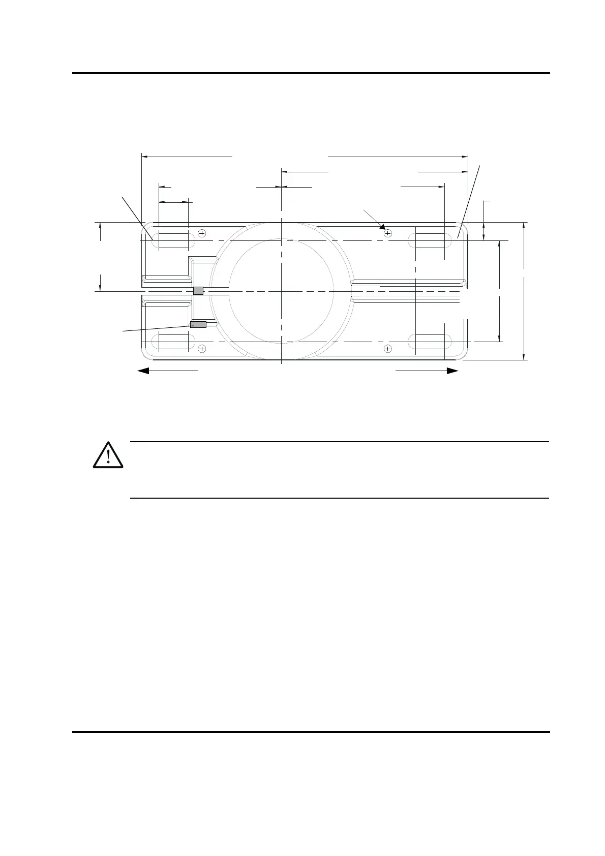
Figure 4.7 Mounting Bolt Pattern for the Hub (for Stand on Hub)
1. Locate the hub in the desired location. Ensure no overhead or side obstructions will interfere with
normal operation or use of the system.
Mount the hub to your work surface using four bolts, 3/8-inch or M10 shank size, with flat
washers against its metal casting (customer provided hardware).
2. Carefully lift the actuator and column assembly, and mount the column in the hub. Align the flat face
of the spring swivel with the top-front of the actuator. Tighten the two bolts on the hub.
3. Connect factory air to the air hose on the stand (3/8 NPT male fitting on the hose). A quick-
disconnect fitting is suggested. Use a lockout device on the air line if required.
4. Verify the base/start switch control cable is properly connected to the back of actuator.
5. Verify the linear encoder connector is properly connected to the back of the actuator.
6. Use jack screws to fine adjust the system level. A 3/16" allen wrench should be used for the 3/8"-
16 x 3/4" jack screws.
4.5.3 Actuator (alone)
The actuator (alone) is intended for installation on your custom-made mounting support. It is located in place
with a mounting pin and secured using three metric bolts which are provided with the actuator.
10.50 in / 267 mm
6.00 in / 152 mm
5.25 in / 133 mm
0.94 in / 24 mm
(four places)
3.25 in /
83 mm
4.44 in /
113 mm
3.94 in / 100mm
2.22 in /
56 mm
0.59 in /
11 mm
3/8 inch or
M10 bolts
Front of Hub
Column
Bolts
(4 places)
Jack Screws(4)
Front of Hub
Rear of Hub