2000X energy Power Supply Chapter 7: Maintenance
Instruction Manual Parts Replacement
011-003-991 EN 7-53
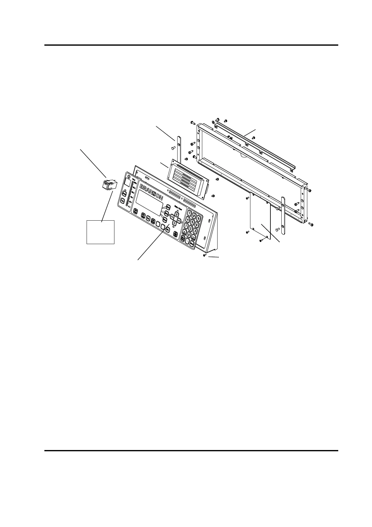
Figure 7.4 Front Panel, Exploded Parts View
7.7.2 Circuit Boards and Modules
Replaceable Modules are shown in Figure 7.3, Exploded View of all 2000 Modules. Ribbon cables and con-
nectors are unique and keyed to prevent the misconnection of an appropriate connector in a location within
the Power Supply case. Fans use identical wiring harnesses, with one tying back the ‘extra’ lead length.
Make note of any wiring paths if you are removing a module, before you disassemble. In some cases, there
are several possible paths, but one preferred location. Be especially careful with harnesses and wires that
go between the two portions of the case, as they can be pinched by the metal case if mis-routed.
Front Bezel Support
(4 Screws from back, inside)
VFD Display Unit
EDP 200-220-014
Front Corner Plate (2 places)
(removed when Rack Mount)
Power Switch and Lamp Assembly
EDP 200-099-252
BLK
YEL
GRY BLU
BRN
Bottom view of PS Switch
color code for 5 leads
Note: Membrane and Front Bezel,
EDP 100-246-1055, are only replaceable as a unit.
Screws (5)
Blank Plate