Chapter 7: Maintenance
Parts Replacement
7-56 011-003-991 EN
7.7.6 DC Power Supply
The DC Power Supply is mounted to the rear of the Power Supply case. It is mounted so it will swivel up to
service the DC Power Supply, Line Board, and fuses. See Figure 7.3, Exploded View of all 2000 Modules.
To remove the DC Power Supply, take the following steps:
To reinstall the DC Power Supply, reverse the removal procedure.
When reconnecting wires, observe the color coding that you previously noted. When installing
the connectors, to TB1 and TB2, ensure the wires from the connectors are turned toward the
outside of the unit.
7.7.7 User I/O Board
The User I/O Board is the short interface board. It is mounted to the System Controller Board on standoffs,
and is connected to the rear of the Power Supply case by its end panel.
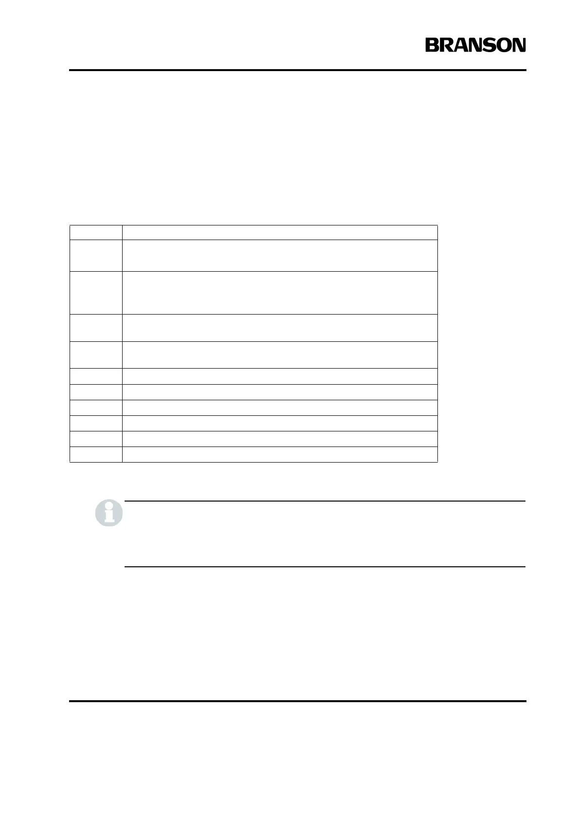
Table 7.14 Removing the DC Power Supply
Step Action
1 Turn off the Power Supply.
Unplug the main power.
2
Using a #2 Philips screwdriver, remove 7 screws from the 2000X cover
(3 on each side, 1 on the rear). Remove the cover.
Allow at least two minutes for capacitor discharge.
3
Using a #1 Philips screwdriver, on the top of the DC Power Supply,
remove 1 rear screw.
4
Using a #1 Philips screwdriver, on the left side of the DC Power Supply,
remove the rear screw.
5 Rotate the DC Power Supply up to allow you access to connectors.
6 Disconnect the 5-pin connector (TB1).
7 Disconnect the 16-pin connector (TB2).
8 Disconnect pin 5 (red) and pin 6 (black) noting the wire colors.
9 On the top of the DC Power Supply, remove 4 screws.
10 Remove the DC Power Supply.