Chapter 4: Installation and Setup
Start Switch Connection (Automation)
4-24 011-003-991 EN
4.6 Start Switch Connection (Automation)
See Appendix E for additional information about Automation.
A Branson actuator requires 2 start switches and emergency stop connection. Stands on a base include this
connection (factory installed and connected from the base) while the stand on a hub and actuator (alone)
applications require the user make their own start switch/E-stop connections, as follows:
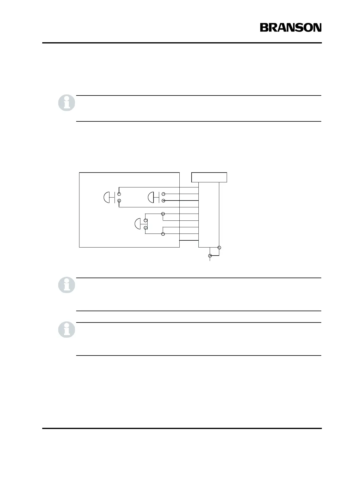
Figure 4.11 Start Switch Connection Codes
Solid state devices may be used in lieu of mechanical start switches providing their leakage
current does not exceed 0.1mA.
Start Switches PB1 and PB2 must be closed within 200 milliseconds of each other, and
remain closed until the WELD ON signal is active, to effect a start condition.
BASE/START is the DB-9 female connection on the back of the actuator. Your cable requires a male DB-9
(D-shell) connector.
P69
EMER
STOP
START SWITCHES
PB1PB2
1
2
3
4
5
6
7
PB2RTN
8
9
Color Codes
Blue
Black
PB1RTN White
PB1SRC
PB2SRC Orange
ESTOPSRC Yellow
ESTOPSRC Purple
ESTOPRTN
ESTOPRTN Red
Green
N/C Brown