3-69
Confidential
■ When there are two Valve ASSYs in the Supply valve ASSY
(1) Cover the Ink full sensor PCB ASSY with a cloth etc. so that ink and/or pre-coat ink will
not be affixed to the Ink full sensor PCB ASSY on the top of the Sub tank at the ink flow
channel side.
(2) Loosen the four Taptite cup S M3 x 6 SR screws in the Supply pump ASSY.
Fig. 3-68
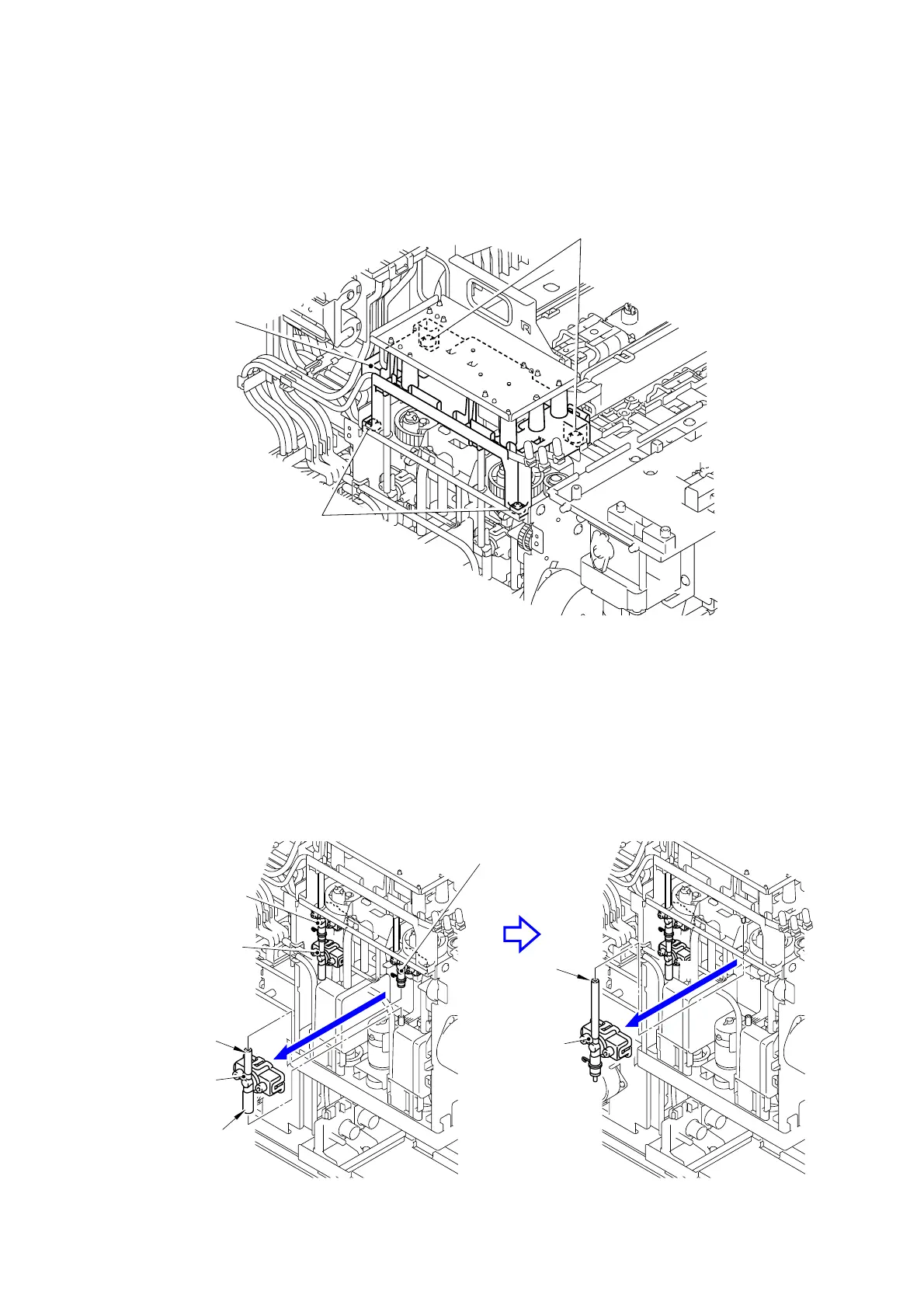
(3) Remove the intermediate joint of two Valve ASSYs in the Supply valve ASSY at the
pre-coat ink flow channel side, and cover the intermediate joint of the upper Valve ASSY
with a cloth, etc. to prevent it from getting dirty due to the pre-coat ink leakage.
(4) Remove the Tube at the lower side of the lower Valve ASSY in the Supply valve ASSY at
the pre-coat ink flow channel side from the joint of the Sub tank and remove the lower
Valve ASSY. Cover the end of the Tube at the lower side of the lower Valve ASSY with a
cloth, etc. to prevent it from getting dirty due to the pre-coat ink leakage.
(5) Remove the Tube at the upper side of upper Valve ASSY in the Supply valve ASSY at the
pre-coat ink flow channel side from the L joint of the Tube coming from the Ink refill unit
and remove the upper Valve ASSY.
Fig. 3-69
Taptite cup S M3x6 SR
Taptite cup S M3x6 SR
Supply pump ASSY
Tube at the
Tube at the
4
5
Joint
upper side
lower side
Valve ASSY at
the ink flow
channel side
(upper side)
Valve ASSY at the
pre-coat ink flow
channel side
Valve ASSY at the
pre-coat ink flow
channel side
Valve ASSY at
the ink flow
channel side
(lower side)
Valve ASSY at the pre-coat ink flow
channel side (upper side)
(upper side)
(lower side)

 Loading...