DETAILED STEPS
Step 1
At the rear of the router, check that the power supply Standby switch is in the Standby (see Figure 105: Cisco ASR 1002
Router –48 VDC Power Supply Terminal Block Cable Connections, on page 263 ) position.
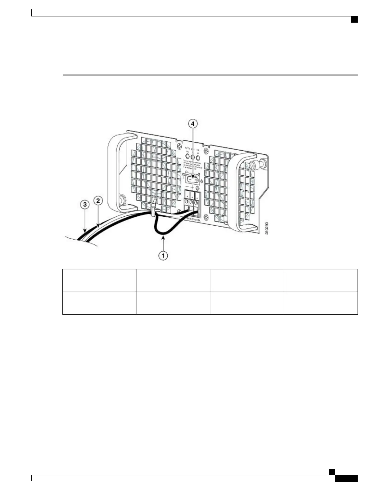
Figure 105: Cisco ASR 1002 Router
–
48 VDC Power Supply Terminal Block Cable Connections
Negative lead3Ground lead with service
loop and tie-wrap
1
–48 VDC power supply
Standby switch
4Positive lead2
Step 2
Ensure that the negative and positive leads are disconnected from the site power source.
Step 3
Using a wire stripper, strip approximately 0.55 inch (14 mm) from the negative, positive, and ground lead.
Step 4
Insert the stripped end of the ground lead all the way into the ground lead receptacle on the –48 VDC input power supply,
and tighten the receptacle screw using a 3.5mm flat-blade screwdriver to a torque of 0.5 to 0.6Nm.
Step 5
Insert the stripped end of the positive lead all the way into the positive lead receptacle and tighten the receptacle screw
using the same 3.5mm flat-blade screwdriver. Repeat this step for the negative lead.
Make sure the entire stripped end of each lead is inserted all the way into its receptacle. If any exposed wire at
the stripped end of a lead is visible after inserting the lead into its receptacle, remove the lead from the receptacle,
use the wire stripper to cut the stripped end of the lead, and repeat Step 3 through Step 5.
Note
Step 6
After tightening the receptacle screw for the ground, positive, and negative –48 VDC-input leads, use a cable tie to secure
the three leads to the power supply faceplate, as shown in the image. When securing the ground, positive, and negative
–48 VDC-input leads to the power supply faceplate, leave a small service loop in the ground lead to ensure that the
Cisco ASR 1000 Series Router Hardware Installation Guide
263
Cisco ASR 1002 Router Overview and Installation
Connecting 48 VDC Input Power to Cisco ASR 1002 Router
 Loading...


