EasyManuals Logo

Cisco ASR 1002-X Hardware Installation Guide

Cisco ASR 1002-X
702 pages
To Next Page IconTo Next Page
To Previous Page IconTo Previous Page
Page #303 background imageLoading...
Page #303 background image
Step 7
After the lead wire is fully inserted, hold the lead wire in place by pressing inward while you remove the screwdriver to
release the spring to tension down on the installed lead wire, then perform these steps:
a) Hold the lead wire in place while you are removing the screwdriver.
b) Once the screwdriver is completely removed, gently pull on the lead wire to make certain that the lead wire is securely
installed.
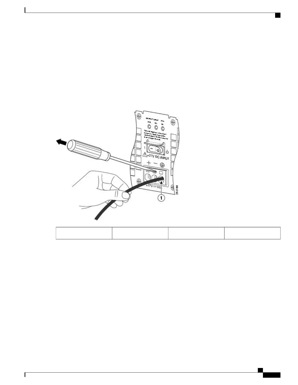
The following shows a lead wire fully inserted, and the screwdriver being removed while you gently pull on the lead
wire.
Figure 111: Removing a Screwdriver from the +24 VDC Power Supply Terminal Block
Gently pull on lead wire.1
Step 8
Repeat Steps 5 through Step 10 for each lead wire.
Cisco ASR 1000 Series Router Hardware Installation Guide
269
Cisco ASR 1002 Router Overview and Installation
Connecting Cisco 24 VDC Power Supply

Table of Contents

Other manuals for Cisco ASR 1002-X

Questions and Answers:

Question and Answer IconNeed help?

Do you have a question about the Cisco ASR 1002-X and is the answer not in the manual?

Cisco ASR 1002-X Specifications

General IconGeneral
Form FactorRack-mountable
Rack Units2RU
Integrated ServicesYes
Maximum Memory16 GB
Built-in Gigabit Ethernet Ports6
Input Voltage100-240 VAC
Operating Temperature32 to 104°F (0 to 40°C)
RedundancyPower supply redundancy
Network Interface ModulesUp to 4 SPA/SIP slots
Embedded Services Processor (ESP)ESP-20
Maximum Packet per Second (PPS)15 Mpps
Height3.5 inches
Fixed Ports6 GE ports
Memory4 GB (default), 16 GB (maximum)
Power SupplyDual power supplies (AC or DC)
Dimensions (H x W x D)3.5 x 17.5 x 19.0 in (8.9 x 44.5 x 48.3 cm)

Related product manuals