DETAILED STEPS
Step 1
Align the cable-management bracket to the rack-mount bracket on one side of the Cisco ASR 1002-F Router. The
cable-management bracket aligns to the top hole of the chassis rack-mount bracket.
Step 2
Insert one screw through the top screw hole of the cable-management bracket and into the chassis rack-mount bracket
and tighten the screw using a Phillips screwdriver.
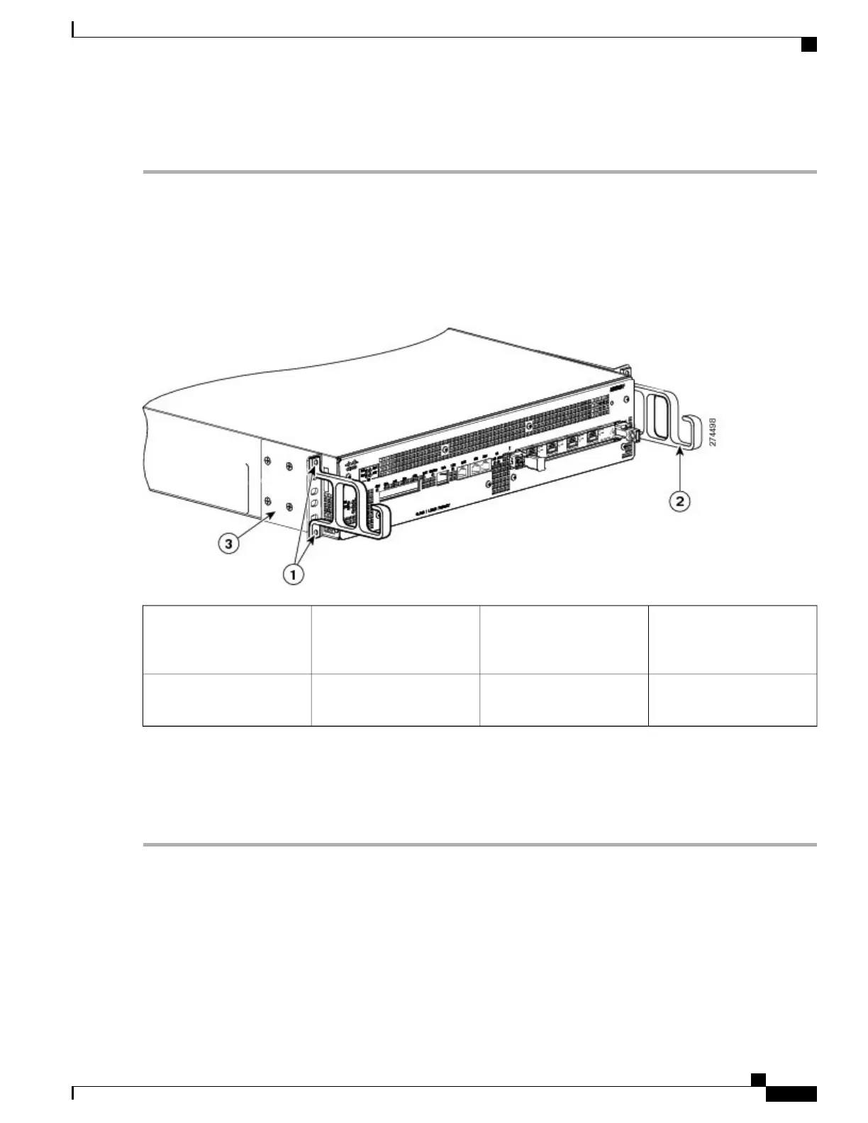
The following image shows where to attach the cable-management brackets to the Cisco ASR 1002-F Router.
Figure 131: Attaching the Cable-Management Brackets to the Cisco ASR 1002-F Router
Chassis front rack-mount
bracket
3Cable-management bracket
top screw hole and bottom
screw hole
1
——
Cable-management bracket
“U” feature
2
Step 3
Insert one screw through the bottom screw hole of the cable-management bracket and into the chassis rack-mount bracket
and tighten the screw using a Phillips screwdriver (see Figure 131: Attaching the Cable-Management Brackets to the
Cisco ASR 1002-F Router, on page 301).
Step 4
Repeat Step 1 through Step 3 for the other side of the Cisco ASR 1002-F Router.
What to Do Next
This completes the procedure for installing the cable-management brackets on the Cisco ASR 1002-F Router.
Cisco ASR 1000 Series Router Hardware Installation Guide
301
Cisco ASR 1002-F Router Overview and Installation
Attaching the Cable-Management Bracket
 Loading...


