Figure 162: Cisco ASR 1002-X Router AC Power Supply Labels, on page 353 shows the various parts of the Cisco ASR
1002-X Router AC power supply.
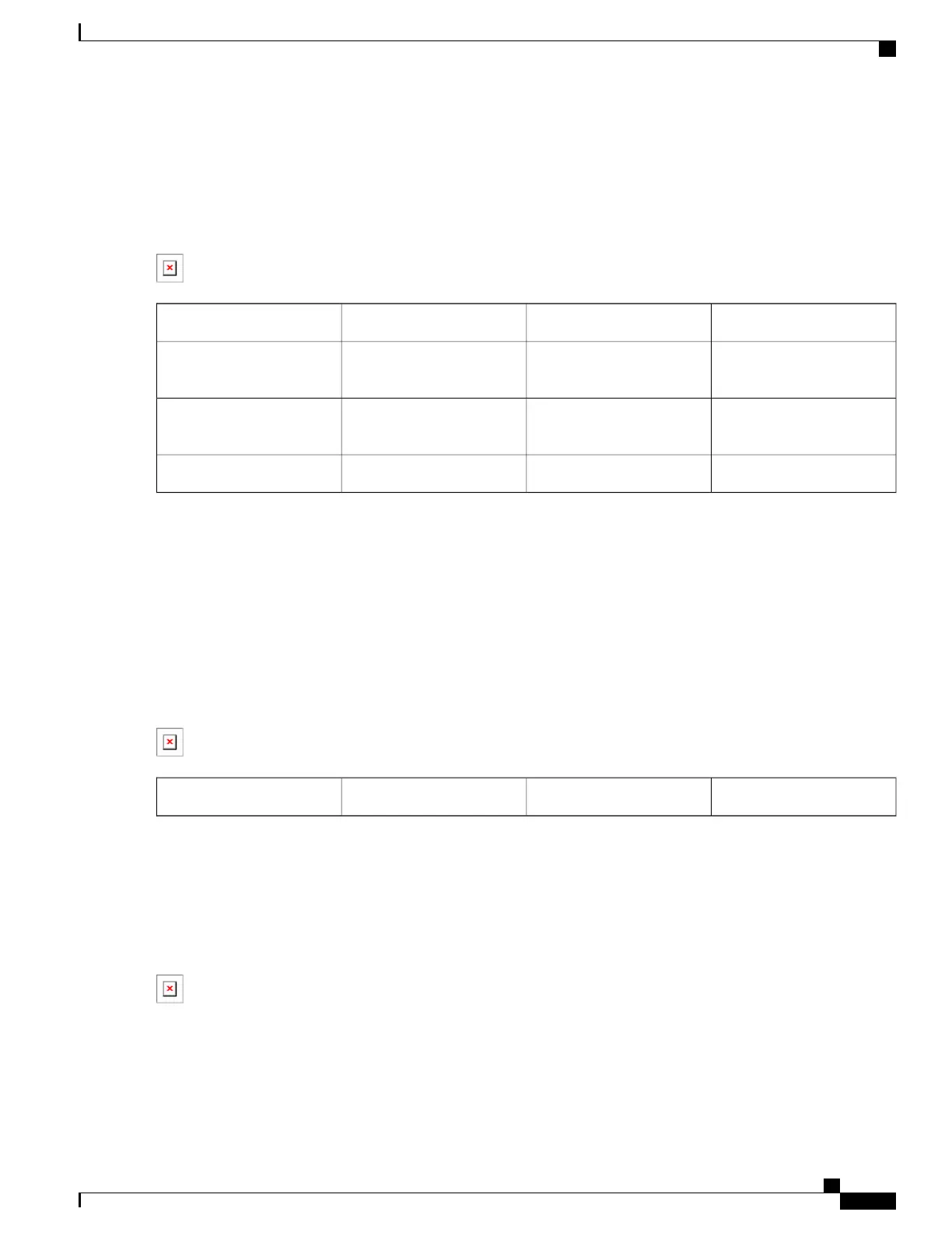
Figure 162: Cisco ASR 1002-X Router AC Power Supply Labels
AC power supply fan5Chassis ESD socket1
AC power supply captive
installation screw
6AC power supply slot
number 0
2
AC power supply slot
number 1
7AC power supply On (|) /Off
(O) switch
3
AC power inlet8AC power supply LEDs4
Step 2
Insert the AC power cable into the power supply AC inlet.
Step 3
To ensure that the AC power cord does not interfere with other cables or wires, dress the AC power cable in one of the
following ways.
•
Leave a small service loop in the AC power cord from the inlet and then secure the power cord through the AC
power supply handle, as shown in Figure 163: Positioning the Cisco ASR 1002-X Router AC Power Supply and
Cord in Slot 1, on page 353.
Figure 163: Positioning the Cisco ASR 1002-X Router AC Power Supply and Cord in Slot 1
AC power cord1
•
Take the power cord and run it below the handles of the right and left power supplies. Make sure the power cord
is hanging loose so that it does not get disconnected from the AC power inlet, as shown in Figure 164: Cisco ASR
1002-X Router AC Power Supply in Slot 0 and Slot 1 with Power Cord, on page 353.
Figure 164: Cisco ASR 1002-X Router AC Power Supply in Slot 0 and Slot 1 with Power Cord
Cisco ASR 1000 Series Router Hardware Installation Guide
353
Cisco ASR 1002-X Router Overview and Installation
Connecting AC Input Power to Cisco ASR 1002-X Router
 Loading...


