EasyManuals Logo

Cisco ASR 1002-X Hardware Installation Guide

Cisco ASR 1002-X
702 pages
To Next Page IconTo Next Page
To Previous Page IconTo Previous Page
Page #577 background imageLoading...
Page #577 background image
Before performing any of the following procedures, ensure that power is removed from the DC circuit.
Statement 1003
Warning
Only trained and qualified personnel should be allowed to install, replace, or service this equipment.
Statement 1030
Warning
Installation of the equipment must comply with local and national electrical codes. Statement 1074Warning
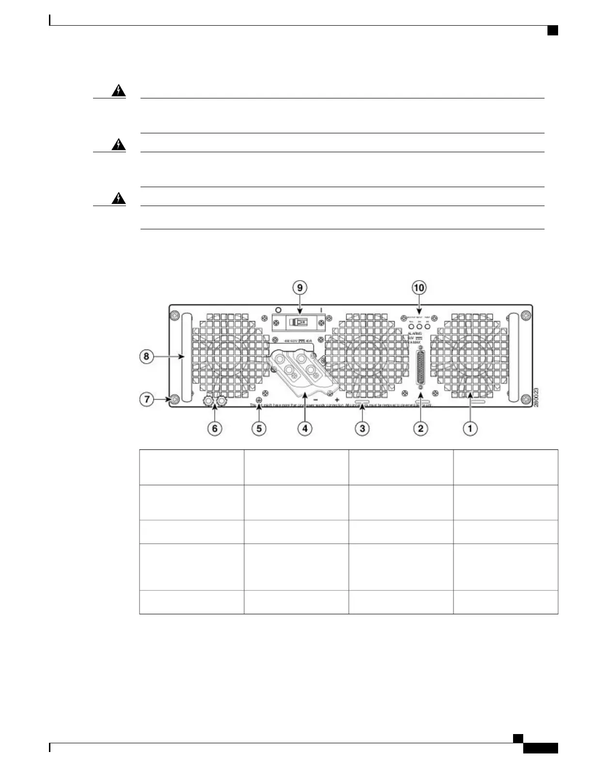
The following figure shows the ASR1006-PWR-DC power supply and components.
Figure 265: Cisco ASR 1006 Router DC Power Supply (ASR1006-PWR-DC)
DC power supply ground
studs
6Fan1
DC power supply captive
screw
7DB-25 alarm connector*2
DC power supply handle8Tie-wrap tab3
On/Off (|/O) circuit
breaker switch
9DC power supply
terminal block and plastic
cover
4
Power supply LEDs10Ground symbol5
Cisco ASR 1000 Series Router Hardware Installation Guide
543
Removing and Replacing FRUs from the Cisco ASR 1000 Series Routers
Removing and Replacing a DC Power Supply in Cisco ASR 1006 Router

Table of Contents

Other manuals for Cisco ASR 1002-X

Questions and Answers:

Question and Answer IconNeed help?

Do you have a question about the Cisco ASR 1002-X and is the answer not in the manual?

Cisco ASR 1002-X Specifications

General IconGeneral
Form FactorRack-mountable
Rack Units2RU
Integrated ServicesYes
Maximum Memory16 GB
Built-in Gigabit Ethernet Ports6
Input Voltage100-240 VAC
Operating Temperature32 to 104°F (0 to 40°C)
RedundancyPower supply redundancy
Network Interface ModulesUp to 4 SPA/SIP slots
Embedded Services Processor (ESP)ESP-20
Maximum Packet per Second (PPS)15 Mpps
Height3.5 inches
Fixed Ports6 GE ports
Memory4 GB (default), 16 GB (maximum)
Power SupplyDual power supplies (AC or DC)
Dimensions (H x W x D)3.5 x 17.5 x 19.0 in (8.9 x 44.5 x 48.3 cm)

Related product manuals