EasyManuals Logo

Cisco ASR 1002-X Hardware Installation Guide

Cisco ASR 1002-X
702 pages
To Next Page IconTo Next Page
To Previous Page IconTo Previous Page
Page #627 background imageLoading...
Page #627 background image
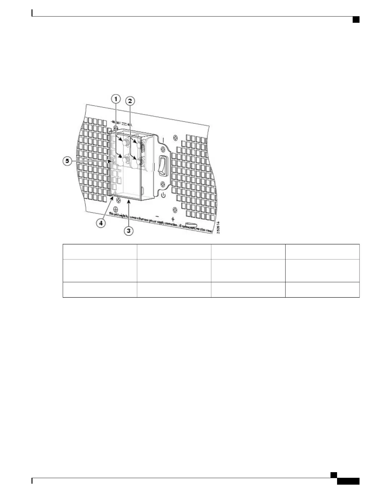
The following figure shows the DC power supply terminal block and plastic cover.
Figure 295: Cisco ASR 1013 Router DC Power Supply Terminal Block and Plastic Cover
Plastic cover slotted area4Negative terminal1
Terminal block plastic cover
single screw
5Positive terminal2
Terminal block plastic cover3
Step 5
Remove the slotted plastic cover from the terminal block (see xref fig).
a) Loosen and remove the single screw on the plastic cover. The plastic cover has slots that help to slide it out diagonally
from the terminal block.
b) Using a nut driver (7/16 size), unsrew the positive kepnut, positive cable, and the flat washer, in that order. The
terminal block houses two double-hole barrel lugs.
Cisco ASR 1000 Series Router Hardware Installation Guide
593
Removing and Replacing FRUs from the Cisco ASR 1000 Series Routers
Removing and Replacing a DC Power Supply in Cisco ASR 1013 Router

Table of Contents

Other manuals for Cisco ASR 1002-X

Questions and Answers:

Question and Answer IconNeed help?

Do you have a question about the Cisco ASR 1002-X and is the answer not in the manual?

Cisco ASR 1002-X Specifications

General IconGeneral
Form FactorRack-mountable
Rack Units2RU
Integrated ServicesYes
Maximum Memory16 GB
Built-in Gigabit Ethernet Ports6
Input Voltage100-240 VAC
Operating Temperature32 to 104°F (0 to 40°C)
RedundancyPower supply redundancy
Network Interface ModulesUp to 4 SPA/SIP slots
Embedded Services Processor (ESP)ESP-20
Maximum Packet per Second (PPS)15 Mpps
Height3.5 inches
Fixed Ports6 GE ports
Memory4 GB (default), 16 GB (maximum)
Power SupplyDual power supplies (AC or DC)
Dimensions (H x W x D)3.5 x 17.5 x 19.0 in (8.9 x 44.5 x 48.3 cm)

Related product manuals