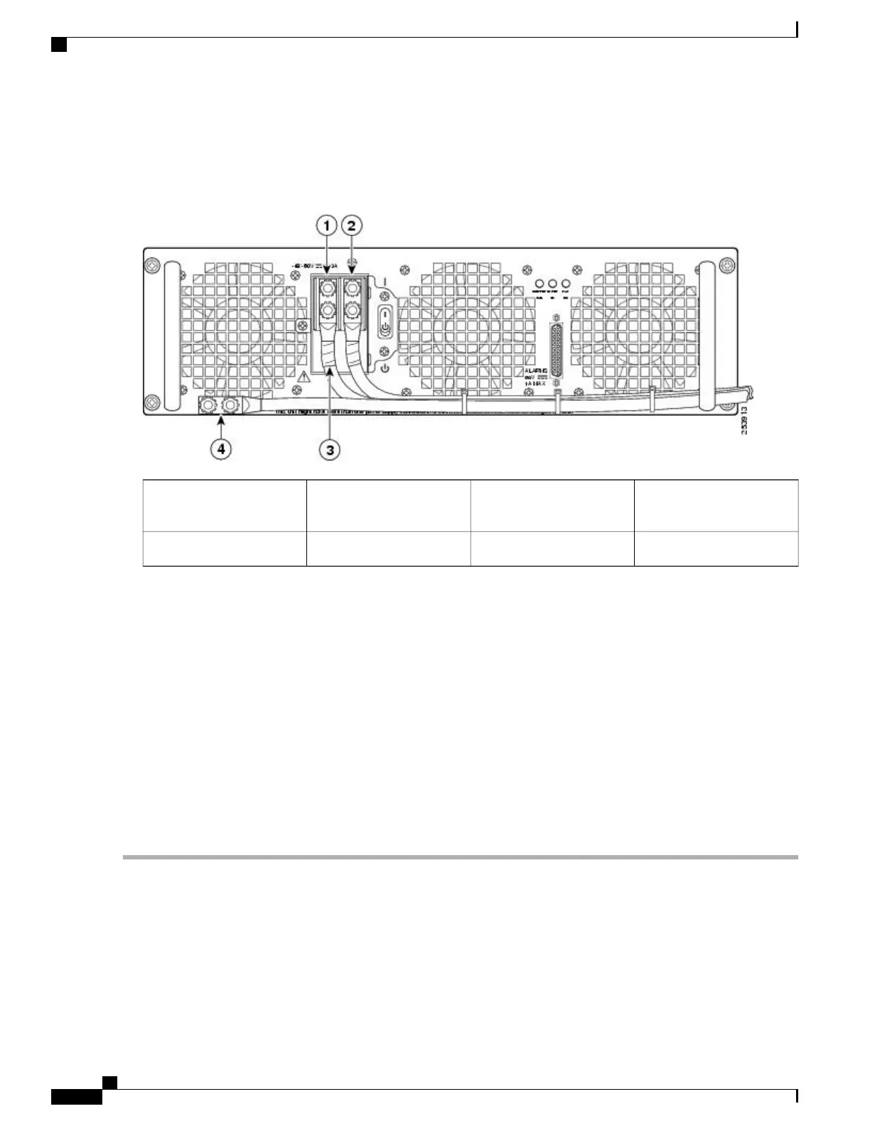
c) Follow Step 4b and remove the negative cable. The following figure shows the DC power supply terminal block.
Figure 296: Cisco ASR 1013 Router DC Power Supply Terminal Block Cable Connections
Protective sleeving around
the stud and cable
3Negative lead1
Ground stud and cable4Positive lead2
When removing the unit, the ground connection must always be made first and disconnected
last.
Warning
Step 6
Loosen the four captive screws on the DC power supply.
Four power supplies must be installed in the chassis at all times, with a minimum of two power supplies (one
per zone) connected to the mains in order to power on the system and ensure sufficient cooling. The system
fans are inside the power supply units and must spin for cooling. Because all the system fans can be powered
by one power supply, the second power supply unit does not have to be powered on, but must be connected.
Note
If you remove a power supply from a system that has four power supplies that are connected and powered
on, the system can run only for a maximum of five minutes before shutting down. However, because the fans
and power elements are independent within the power supply, the replacement power supply does not have
to be energized within five minutes. The only requirement is that the power supply be installed in the chassis
in order to energize the fans and maintain proper system cooling.
Caution
Step 7
Grasping the power supply handles, pull the power supply from the chassis.
Step 8
Replace the DC power supply within five minutes.
What to Do Next
This completes the procedure of removing a DC power supply from the Cisco ASR 1013 Router.
Cisco ASR 1000 Series Router Hardware Installation Guide
594
Removing and Replacing FRUs from the Cisco ASR 1000 Series Routers
Removing and Replacing a DC Power Supply in Cisco ASR 1013 Router
 Loading...


