Parameter
structure
Keypad and
display
Parameter
x.00
Parameter
description format
Advanced parameter
descriptions
Macros
Serial comms
protocol
Electronic
nameplate
Performance
Feature look-
up table
Menu 12
Unidrive SP Advanced User Guide 197
Issue Number: 7 www.controltechniques.com
The variable selectors allow two source values (defined by Pr 12.08, Pr 12.28 and Pr 12.09, Pr 12.29) to be combined as defined by the mode (Pr
12.10, Pr 12.30) to produce an output (Pr 12.12, Pr 12.32) which can be routed to the destination parameter (defined by Pr 12.11, Pr 12.31). The
actions of the variable selector are defined by the mode parameter as given below. If the mode parameter is changed or the variable selector is
disabled because neither source is routed to a valid parameter all the internal state variables (i.e. time constant accumulator, etc.) within the selector
are reset. When the Sectional control mode is selected the function is also reset, and the output is held at zero, when the control (Pr 12.15 or Pr
12.35) is zero. It is active when the control has a non-zero value.
A loss of resolution can be seen when routing paraneter values through the variable selectors due to the maximum available resolution being two
decimal places. The variable select output is scaled to ensure a 100.00% output gives full scale output to the destination parameter. This results in
the destination parameter jumping in steps equivalent to 0.01% resolution if the destination parameter has a greater resolution than two decimal
places.
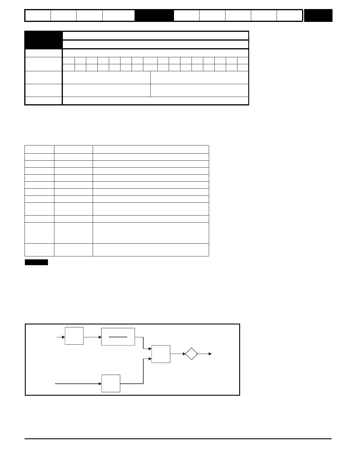
Sectional control
The sectional control function is intended to apply scaling and a speed offset to a 16 bit position value to generate a new 16 bit position value. The
output can be used as an input to the position controller (menu 13) or to generate an encoder simulation output via the SM-Universal encoder plus
module. This function can be selected for either variable selector, but the description below relates to variable selector 1.
The position input can be derived from any parameter, however it is intended to be used with a position value that has a range from 0 to 65535. The
input is scaled so that so that as Pr 12.13 is varied between -4.000 and 4.000 the proportion of the input position change added to the accumulator
varies from 0.000 to 2.000 (i.e. the change of position input value is added without scaling if Pr 12.13 is 0.000). The remainder from the scaling
division is stored and then added at the next sample to maintain an exact ratio between the position input and the position output, provided the speed
input is zero. The controller only takes the change of position from the input source parameter, and not the absolute value, so that when the controller
is first made active the output does not jump to the source position, but only moves with any changes of source position after that point in time.
12.15 Variable selector 1 control
12.35 Variable selector 2 control
Drive modes Open-loop, Closed-loop vector, Servo, Regen
Coding
Bit SP FI DE Txt VM DP ND RA NC NV PT US RW BU PS
2 111
Range
Open-loop, Closed-loop vector, Servo,
Regen
0.00 to 100.00
Default
Open-loop, Closed-loop vector, Servo,
Regen
0.00
Update rate Background
Mode value Action Result
0 Select input 1 output = input1
1 Select input 2 output = input2
2 Add output = input1 + input2
3 Subtract output = input1 - input 2
4 Multiply output = (input1 x input2) / 100.0
5 Divide output = (input1 x 100.0) / input2
6 Time constant output = input1 / ((control param)s + 1)
7 Linear ramp
output = input1 via a ramp with a ramp time of (control
param) seconds from 0 to 100%
8 Modulus output = | input1 |
9 Powers
control = 0.02: output = input1
2
/ 100.0
control = 0.03: output = input1
3
/ 100.0
2
control has any other value: output = input1
10 Sectional control
control = 0.00: disabled, accumulator reset and output
zero control <> 0.00: output as defined below
NOTE
%
4.000 + 12.13
4.000
12.14
Σ
Position
input
Position
output
Speed
input
d/dt
Accumulator
http://nicontrols.com