Menus 15 to 17
Fieldbus
Parameter
structure
Keypad and
display
Parameter
x.00
Parameter
description format
Advanced parameter
descriptions
Macros
Serial comms
protocol
Electronic
nameplate
Performance
Feature look-
up table
278 Unidrive SP Advanced User Guide
www.controltechniques.com Issue Number: 7
menu for the relevant slot appears for the new module category with the default parameter values for the new category. The new parameters values
are not stored in EEPROM until the user performs a parameter save.
This parameter has different behaviour depending on the fieldbus type:
If Pr x.05 = 0 then the input and output cyclic data lengths will be configured independently by Pr x.38, Pr x.39 and Pr x.40.
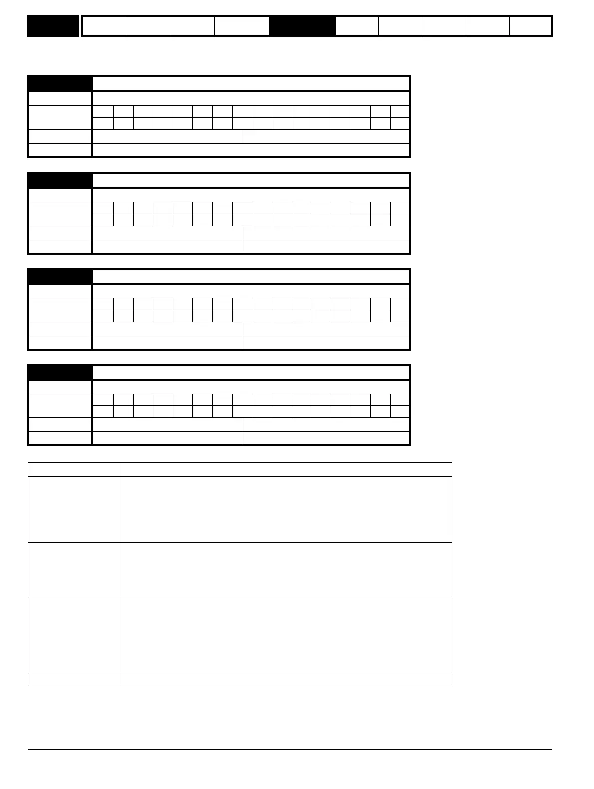
x.02 Option software version
Drive modes Open-loop, Closed-loop vector, Servo, Regen
Coding
Bit SP FI DE Txt VM DP ND RA NC NV PT US RW BU PS
2111 1
Range Open-loop, Closed-loop, Servo, Regen 00.00 to 99.99
Update rate Write on power-up
x.03 Fieldbus Node Address
Drive types Open-loop, Closed-loop vector, Servo, Regen
Coding
Bit SP FI DE Txt VM DP ND RA NC NV PT US RW BU PS
111
Default All drives 65,535
Range All drives 65,535
x.04 Fieldbus Baud Rate
Drive types Open-loop, Closed-loop vector, Servo, Regen
Coding
Bit SP FI DE Txt VM DP ND RA NC NV PT US RW BU PS
11
Default All drives 127
Range All drives -128 to 127
x.05 Mode
Drive types Open-loop, Closed-loop vector, Servo, Regen
Coding
Bit SP FI DE Txt VM DP ND RA NC NV PT US RW BU PS
111
Default All drives 4
Range All drives 65,535
Fieldbus Mode function
SM-PROFIBUS-DP
Sets the number of cyclic words and the format of the non-cyclic channel as follows:
Value = (X
× 100) + Y
X = Non-Cyclic Mode (0 = disabled, 1 = CTNC, 2 = Siemens compatible)
Y = Number of cyclic words (0 = none, 1-28 words)
If Pr x.05 is zero the input and output data lengths, and PPO types can be selected explicitly
– See SM-PROFIBUS-DP documentation for further details.
SM-INTERBUS
Sets the number of cyclic words and the number of words used by PCP
Value = (X
× 100) + Y
X = Non-Cyclic Mode (0 = disabled, 1 = PCP, 2 = CTNC)
Y = Number of cyclic words (0 = none, 1-10 words)
Note: X+Y must be 10 or less
SM-DeviceNet
Sets the number of cyclic words and the format of the non-cyclic channel as follows:-
Value = (X
× 100) + Y
X = Non-Cyclic Mode (0 = disabled, 1 = CTNC, 2 = Siemens compatible)
Y = Number of cyclic words (0 = none, 1-28 words)
If Pr x.05 is zero assembly objects should be explicitly set in Pr x.39 and Pr x.40 – See SM-
DeviceNet documentation for further details.
The maximum amount of polled data that can be transferred is 28 words.
SM-CANopen, SM-CAN To be defined
http://nicontrols.com