Parameter
structure
Keypad and
display
Parameter
x.00
Parameter
description format
Advanced parameter
descriptions
Macros
Serial comms
protocol
Electronic
nameplate
Performance
Feature look-
up table
Menus 15 to 17
Fieldbus
Unidrive SP Advanced User Guide 279
Issue Number: 7 www.controltechniques.com
The trip is primed when cyclic data transfer begins. If there are no cyclic data transfers for a time that is greater than or equal to Pr x.07 a "network
loss" trip will occur. The trip delay time can be entered into Pr x.07 in ms (zero is disabled). A network loss trip will not effect the internal state of the
module, it is only a user indication. The fieldbus specific network management schemes are used to influence the master, and control the state of the
module.
Selects the order of 16 and 32bit data (transferred in the cyclic channels (and non-cyclic channels if fieldbus permits).
Not all fieldbuses support both endian types – See the fieldbus specific documentation for further details.
Pr x.09 through Pr x.29 control how network data is handled depending on the fieldbus type.
Defines how the 'I' and 'O' data registers are handled. If Pr x.05 > 0 then Pr x.09 being set to 1 will result in Pr x.06 showing -3 (Invalid configuration
parameters) and detailed mapping status information will be shown in Pr x.49.
x.06 Fieldbus diagnostic
Drive types Open-loop, Closed-loop vector, Servo, Regen
Coding
Bit SP FI DE Txt VM DP ND RA NC NV PT US RW BU PS
111
Default All drives 0
Range All drives ±9,999
< -10 Fieldbus specific state.
-4 Software error
-3 Invalid configuration parameters.
-2 Fieldbus initialisation failure.
-1 Initialisation complete but no network running.
0 Network running but no network cycles per second detected.
X
Network cycles per second detected. See Fieldbus specific documentation for further details
.
x.07 Trip Delay Time
Drive types Open-loop, Closed-loop vector, Servo, Regen
Coding
Bit SP FI DE Txt VM DP ND RA NC NV PT US RW BU PS
111
Default All drives 200
Range All drives 0 to 3,000
x.08 Endianism
Drive types Open-loop, Closed-loop vector, Servo, Regen
Coding
Bit SP FI DE Txt VM DP ND RA NC NV PT US RW BU PS
111
Default All drive types 0
OFF Big Endianism - MSByte first.
ON Little Endianism - LSByte first.
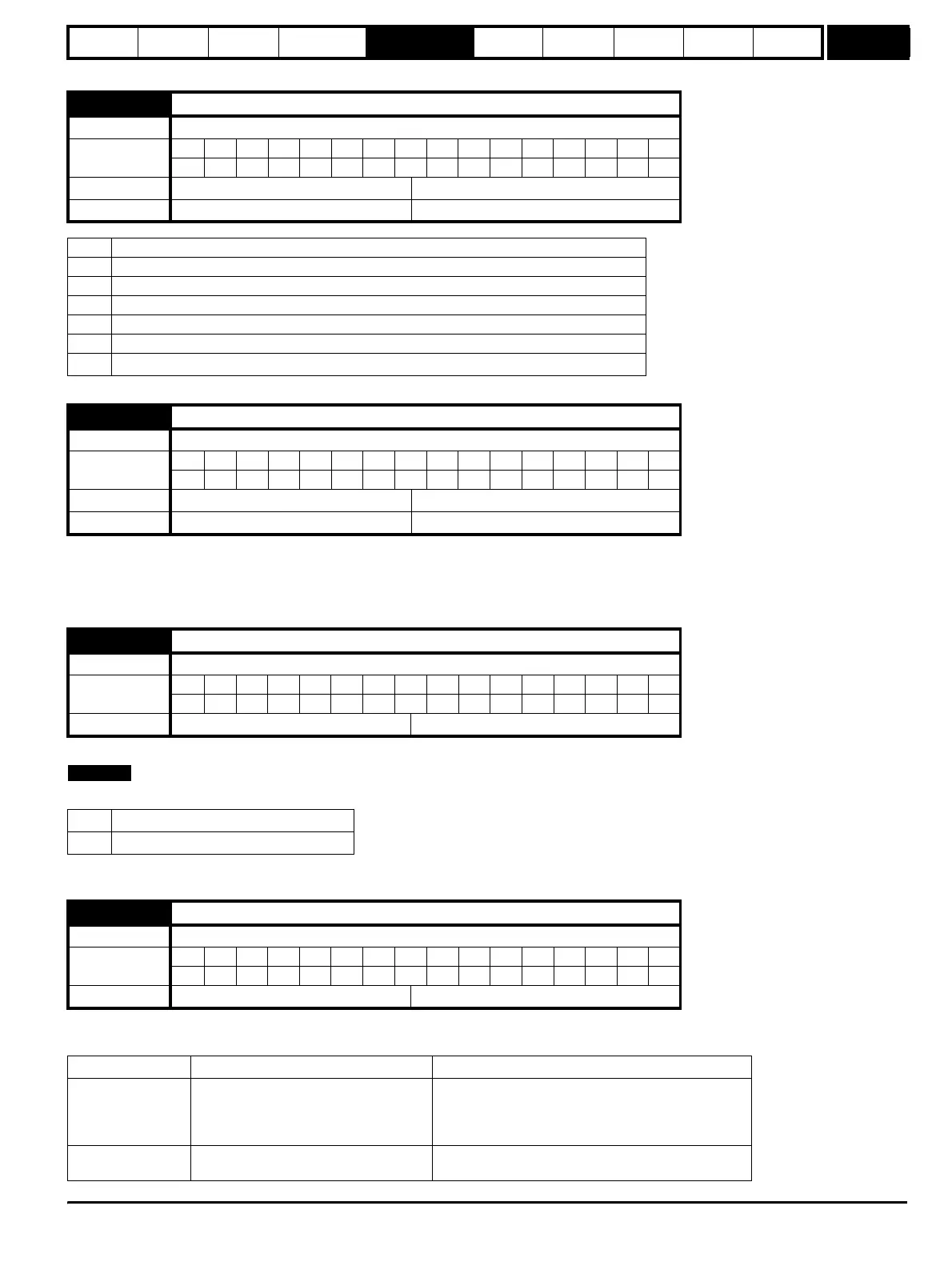
x.09 Register control
Drive types Open-loop, Closed-loop vector, Servo, Regen
Coding
Bit SP FI DE Txt VM DP ND RA NC NV PT US RW BU PS
111
Default All drive types 0
Fieldbus Pr x.09 set to zero Pr x.09 set to 1
SM-INTERBUS
SM-PROFIBUS-DP
SM-DeviceNet
SM-CANopen
I registers (Pr x.10 to Pr x.19) map drive
parameters to PLC IN data registers.
O registers (Pr x.20 to Pr x.29) map PLC
OUT data registers to drive parameters
The values in the I registers (Pr x.10 to Pr x.19) will be
sent to the PLC IN data registers.
Values received from the PLC OUT registers will be
placed directly into the O registers (Pr x.20 to Pr x.29).
SM-CAN
I and O registers are reserved and must
not be used
I and O registers are reserved and must not be used
NOTE
http://nicontrols.com