Parameter
structure
Keypad and
display
Parameter
x.00
Parameter
description format
Advanced parameter
descriptions
Macros
Serial comms
protocol
Electronic
nameplate
Performance
Feature look-
up table
Menus 15 to 17
SM-Applicat’ns
Unidrive SP Advanced User Guide 299
Issue Number: 7 www.controltechniques.com
The priority levels of different tasks may be changed with this parameter. The parameter is accessed bit wise.
Bit 0
The value of 0 will give the same priority levels for tasks as UD70. Setting the value to 1 will reduce the priority of CTNet to below that of POS0 and
POS1. This will reduce the jitter of the POS tasks but could lead to the CTNet task being starved.
Bit 1
The value of 0 will mean that the inter option communication task priority is higher than the POS tasks. Setting the value to 1 will make the inter option
communication task priority lower than the POS tasks.
If a run-time error is logged, this parameter gives the line number (where available) of the DPL statement which caused the error to be raised. If a
value of 0 is shown then the line number is unavailable. If the error was caused by execution of code within a ladder or function block diagram, the line
number shown will be the first source line on which the diagram appears.
General user parameter intended for displaying a user program ID.
The error status is provided so that only one Solutions Module error trip is required for each Solutions Module slot. If an error occurs the reason for
the error is written to this parameter and the drive may produce a SLotx.Er trip, where x is the slot number. A value of zero indicates that the module
has not detected an error, a non-zero value indicates that an error has been detected. (See descriptions for each category for the meaning of the
values in this parameter.) When the drive is reset this parameter is cleared for all Solutions Modules.
All modules include a temperature monitoring circuit. If the PCB temperature exceeds 90°C the drive fan is forced to operate at full speed (for a
minimum of 10s). If the temperature falls below 90°C the fan can operate normally again. If the PCB temperature exceeds 100°C the drive is tripped
and the error status is set to 74.
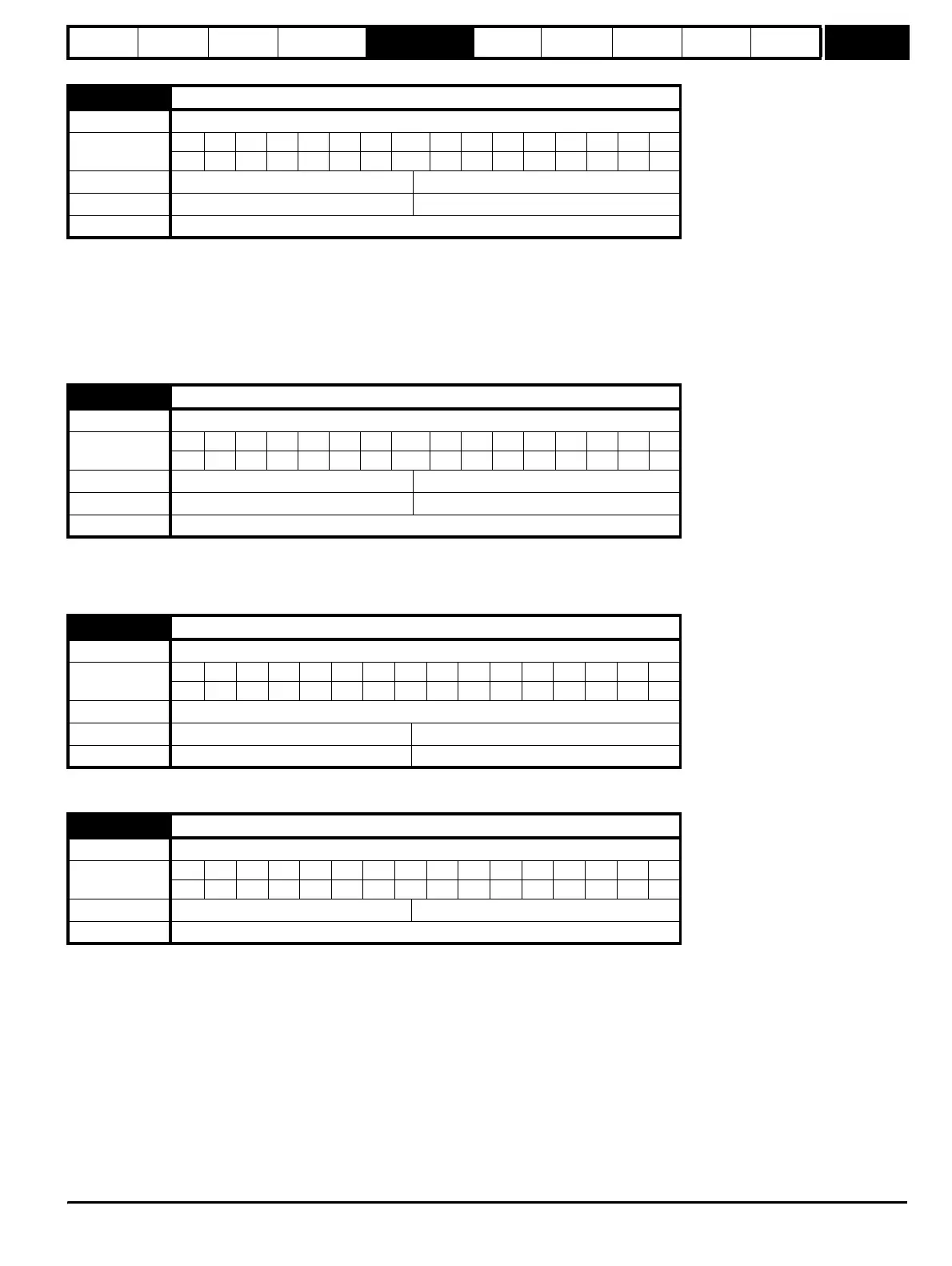
x.44 Task priority level
Drive types Open-loop, Closed-loop vector, Servo, Regen
Coding
Bit SP FI DE Txt VM DP ND RA NC NV PT US RW BU PS
111
Default All drives 0
Range All drives 0 to 255
Update Rate Not Applicable
x.48 DPL line number in error
Drive types Open-loop, Closed-loop vector, Servo, Regen
Coding
Bit SP FI DE Txt VM DP ND RA NC NV PT US RW BU PS
11
Default All drives 0
Range All drives 0 to 2,147,483,647
Update Rate Not Applicable
x.49 User program ID
Drive types Open-loop, Closed-loop vector, Servo, Regen
Coding
Bit SP FI DE Txt VM DP ND RA NC NV PT US RW BU PS
11
Coding RW
Default All drives 0
Range All drives -32,768 to +32,767
x.50 Solutions Module error status
Drive modes Open-loop, Closed-loop vector, Servo, Regen
Coding
Bit SP FI DE Txt VM DP ND RA NC NV PT US RW BU PS
111 1
Range Open-loop, Closed-loop, Servo, Regen 0 to 255
Update rate Background write
http://nicontrols.com