Menus 15 to 17
SM-Applicat’ns
Parameter
structure
Keypad and
display
Parameter
x.00
Parameter
description format
Advanced parameter
descriptions
Macros
Serial comms
protocol
Electronic
nameplate
Performance
Feature look-
up table
298 Unidrive SP Advanced User Guide
www.controltechniques.com Issue Number: 7
The drive controls bit 0 of the synchronisation status to indicate whether the particular Solutions Module is the synchronisation master. Once the
Solutions Module is the synchronisation master it remains the master unless another module requests to be the master and the request is granted or
the synchronisation mode request is set to zero. If the Solutions Module is synchronisation master and stops providing a synchronisation waveform
the synchronisation system continues to run, but the frequency remains constant. If the Solutions Module produces a synchronisation frequency that
is out of specification the synchronisation system runs at the limit of the tolerance until a signal is produced that is within the specification. The
synchronisation system status is monitored by a counter. The counter is set to zero at when the synchronisation system is not active and at power-up,
and can count up or down once every 4ms in the range between 0 and 32. If the synchronisation waveform is present and within specification the
counter counts up otherwise it counts down. When the counter has a value of 16 or more status bit 1 is cleared otherwise it is set.
The user will be able to automatically transfer predefined data.
In master mode 0 the values of Pr 91.13 and Pr 91.14 can be loaded with user defined values. The delay will be the position loop rate plus 250µs.
In master mode 1 the values of Pr 90.01 and Pr 90.02 will be placed in Pr 91.13 and Pr 91.14. This will ensure that the slave gets the position
reference of the master with the minimum delay (250µs).
In master mode 2 the MSW of Pr 90.01 and Pr 90.02 will be placed in Pr 91.13 and the speed reference (Pr 3.22) in Pr 91.14. This will ensure that the
slave gets the position and speed references of the master with the minimum delay (250µs).
In master mode 3 the Pr 90.01 will be placed in Pr 91.13 and the speed reference (Pr 3.22) in Pr 91.14. This will ensure that the slave gets the
position and speed references of the master with the minimum delay (250µs).
When a freeze occurs on the Solutions Module the main drive position can also be stored if this parameter is set to one.
When Pr x.43 = 0 freeze occurs on the rising edge of the freeze input. When Pr x.43 = 1 freeze occurs on the falling edge of the freeze input.
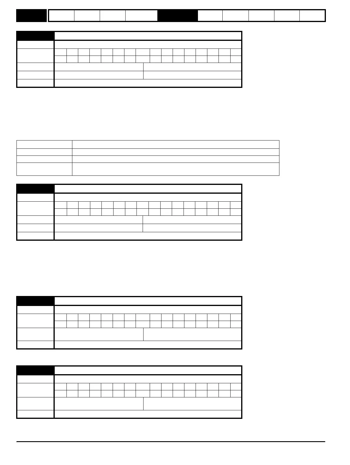
x.39 Inter-SM-Applications drive synchronisation status ♣
Drive types Open-loop, Closed-loop vector, Servo, Regen
Coding
Bit SP FI DE Txt VM DP ND RA NC NV PT US RW BU PS
11
Default All drives 0
Range All drives 0 to 3
Update Rate Not Applicable
Synchronisation status Status
0 The synchronisation master request is zero or another Solutions Module is synchronisation master
1 The Solutions Module is synchronisation master
3
The Solutions Module is synchronisation master, but the synchronisation frequency is out of
specification or not present
x.40 Inter-SM-Applications master transfer mode ♣
Drive types Open-loop, Closed-loop vector, Servo, Regen
Coding
Bit SP FI DE Txt VM DP ND RA NC NV PT US RW BU PS
111
Default All drives 1
Range All drives 0 to 10
Update Rate Not Applicable
x.42 Freeze main drive position ♣
Drive types Open-loop, Closed-loop vector, Servo, Regen
Coding
Bit SP FI DE Txt VM DP ND RA NC NV PT US RW BU PS
1111
Default
Open-loop, Closed-loop vector, Servo,
Regen
0
Update Rate Not Applicable
x.43 Freeze invert ♣
Drive types Open-loop, Closed-loop vector, Servo, Regen
Coding
Bit SP FI DE Txt VM DP ND RA NC NV PT US RW BU PS
111
Default
Open-loop, Closed-loop vector, Servo,
Regen
0
Update Rate Not Applicable
http://nicontrols.com