MECHANICAL INSTALLATION
It provides approximately 300 mm [12 in] minimum clearance on all sides. This clearance
is necessary to provide proper ventilation, allow access to all panels of the barcode
reader, and allow room for proper servicing.
2.4.6 Scanning Station Frame/Mounting Structure Preparation and
Positioning
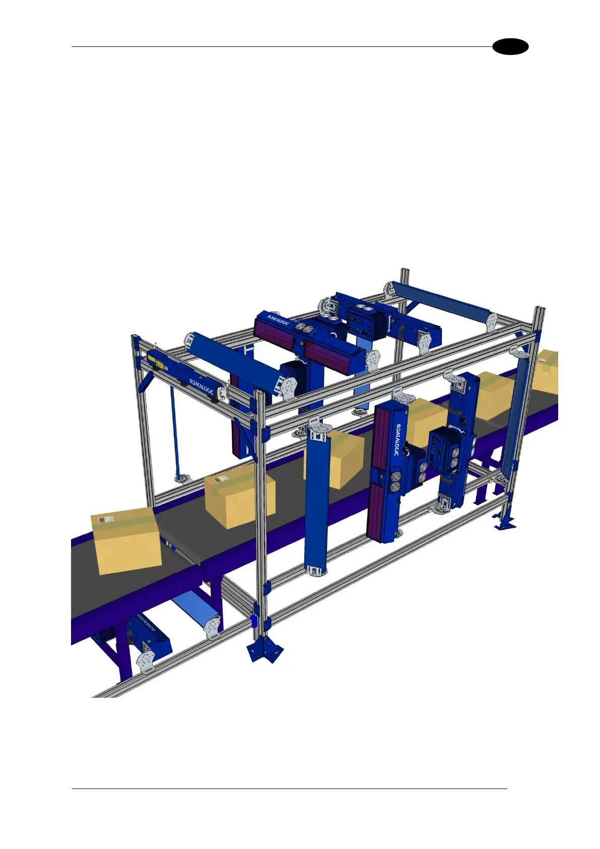
The vision system components and in particular the mounting brackets have been designed
for installation onto standard Bosch and 80/20 frame profiles (extrusions) and accessories.
60x60 mm profile is recommended for Bosch, although 45x45 mm profiles will work; and
standard 1.5” x 3” for 80/20.
Figure 22: Example Station Frame Layout

 Loading...

