ELECTRICAL INSTALLATION
3.11 CBX510 CONNECTION BOX
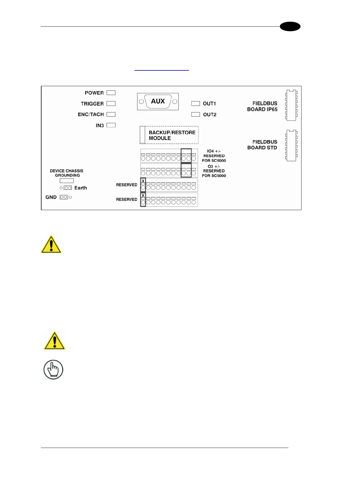
Complete installation information for the connection box is available in the CBX510
Installation Manual available at www.datalogic.com. A simple drawing of the interior of the
box is shown below.
Figure 77: CBX510 Interior
IMPORTANT: If you are terminating more than one wire in a single
terminal, cut off any tinned ends and twist the wires together before
inserting them into the terminal.
3.11.1 Photoelectric Sensor Connections to CBX510
Barcode scanning applications may use a Datalogic photoelectric sensor as a trigger device.
The photoelectric sensor is wired directly into the CBX510 terminal block.
If your application uses a trigger other than the one specified by Datalogic, follow the
appropriate wiring diagram to assure proper wiring.
IMPORTANT: You must use shielded interface cables with this
product. To maintain FCC compliance, the cable shield must make a
360-degree connection to the shielded mating connector.
NOTE: To confirm the photoelectric sensor is functioning properly,
watch the TRIGGER LED first in the CBX and then on the camera
while the photoelectric sensor’s beam is blocked. The Datalogic
photoelectric sensor also includes a status LED.
The following diagrams illustrate standard recommended wiring of the Photoelectric Sensor
to the CBX510 terminal block.

 Loading...

