ELECTRICAL INSTALLATION
3.6 CONNECTING A PC TO THE AV7000
During initial setup, a PC (laptop) may be connected to the AV7000 with an RJ45 cable.
Connect an Ethernet cable from the HOST NET or IMAGE NET port of the AV7000 to the
Ethernet port of your PC. For information on connect to e-Genius, see Chapter 4.
NOTE: Parameters for tunnel are set up in the MASTER AV7000 only.
NOTE: IP Address for HOST NET and IMAGE NET are as follows:
HOST NET – 192.168.3.10
IMAGE NET – 10.0.40.20
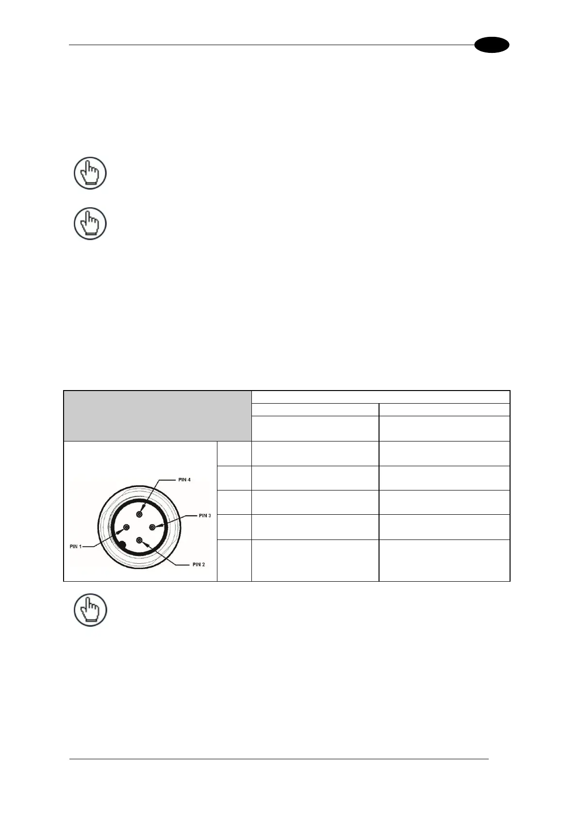
3.7 POWER CONNECTOR PIN-OUT TABLE
A recommended power supply and cabling is available for the AI7000 Illumination, which
then supplies the AV7000 Camera. However, if your installation requires custom power
supply wiring, the pin-outs of the AV7000 camera power connector are provided below your
convenience.
NOTE: When using an AI7000 Illumination and AV7000 Camera, no
power supply is required for the CBX connection box. All power and
some communication options are fed to the CBX through the
AV7000’s 19-pin I/O connector to the CBX 25-pin connector using
the cable provided.

 Loading...

