AV7000 LINEAR CAMERA REFERENCE MANUAL
3.10 CBX100/CBX500/CBX800 CONNECTION BOX INITIAL
CONFIGURATION
Complete installation information on these connection boxes is available in the CBX100,
CBX500, and CBX800 Installation Manuals available at www.datalogic.com.
CBX100
Please verify that the CBX100 connection box is configured for the AV7000 application as
follows:
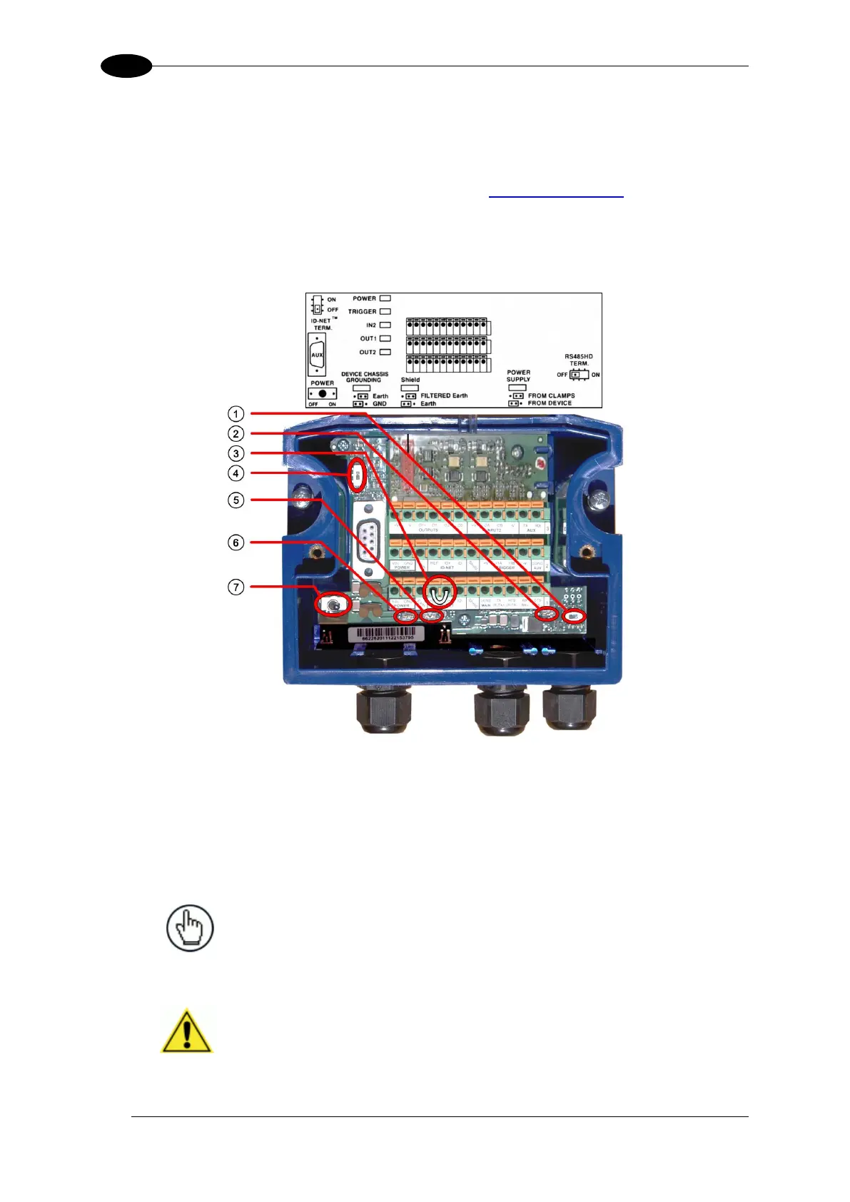
Figure 63: CBX100 Initial Setup
Reference the image and diagram above:
1. Set RS422HD TERM switch to OFF.
2. Set POWER SUPPLY jumper to FROM DEVICE.
3. Insert jumper wire in pin block from REF to ID+ (one jumper in either block is
sufficient).
NOTE: In order for a standalone or Master AV7000 to initialize properly, it
must be connected to a CBX100. On power-up the AV7000 looks for the
jumper (item number 3 in the image above) and will assume the responsibility
of providing the SYNC Network IP addresses. Slave units in an array/tunnel
will receive their SYNC Network IP addresses from the Master.
IMPORTANT: Although multiple AV7000 cameras can have a CBX
box, only one of the CBX boxes in a multi-camera system can have
the Jumper to make it the Master.

 Loading...

