AV7000 LINEAR CAMERA REFERENCE MANUAL
3.8 POWER CONNECTIONS
IMPORTANT: When planning your installation wiring, remember all
power connections must be quick-disconnect.
CAUTION: While performing the following wiring connection
procedures, be sure to follow all safety procedures regarding high-
voltage as outlined in the Introduction to this manual. No power
should be applied to any device until all wiring is completed and
checked for accuracy.
IMPORTANT: The socket-outlet must be installed near the barcode
reader. The outlet must be a readily accessible disconnect device.
GROUND: Ground the barcode reader to safety ground (protective
earth ground (PE)). See section 3.12 for wiring recommendations for
safety ground.
The CBX connection boxes provide flexible connectivity to a range of I/O devices as well as
serial hosting. The AV7000 connects to the CBX via its I/O port using a single 19-pin M16 to
25-pin D cable.
3.8.1 Power Supplies and Supply Capacity When Wiring to AI7000s
One PG-600 is able to power:
one AI7000 illuminator (including the AV7000 camera which is powered via this unit and
one CBX510 with all the standard sensors)
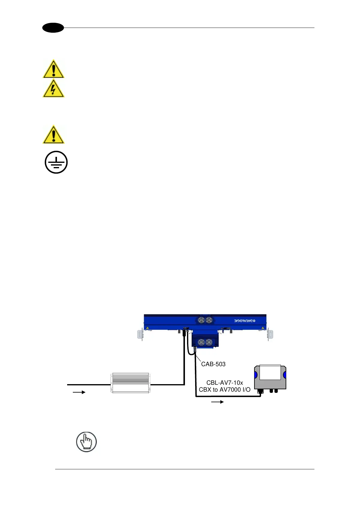
The power supply unit is connected to the camera illuminator according to the following
diagram (power supply side):
Figure 60 - Connecting PG-600 to AI7000 Illuminator
NOTE: If the PG-600 is mounted further than 1 M [3 ft] from
the AV7000/AI7000, use the CVL-2389 power extension
cable include in the illuminator package.
CBL-AV7-10x
CBX to AV7000 I/O

 Loading...

