ELECTRICAL INSTALLATION
The CBX510 connection box receives power through the CBL-AV7-10x from the AV7000 IO
connector.
One PWR-480B is able to power:
one AI7000 illuminator (including the AV7000 camera which is powered via this unit and
one CBX510 with all the standard sensors)
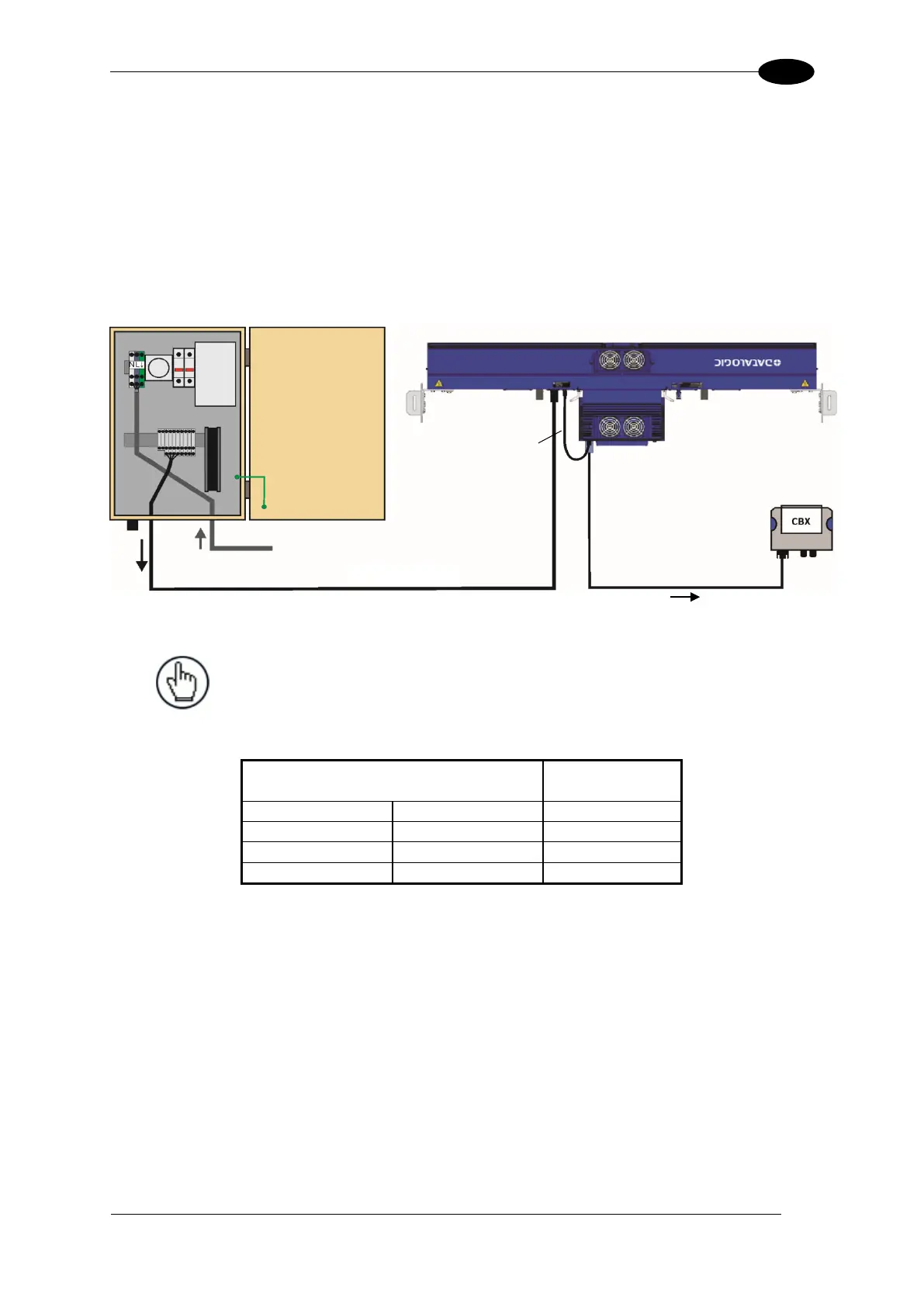
The power supply unit is connected to the camera illuminator according to the following
diagram (power supply side):
Figure 61 - Connecting PWR-480B to AI7000 Illuminator
NOTE: The AI7000 series illuminators are supplied with a CVL-2389
extension power cable. Use this cable to connect the PWR-480B power
supply by cutting off the cable’s male Amphenol connector and
connecting the wires to the PWR-480B according to the table below:
CVL-2389 Wire Color or Number
(Depending on Source)
The CBX510 connection box receives power through the CBL-AV7-10x from the AV7000 IO
connector.
CBL-AV7-10x
CBX to AV7000 I/O

 Loading...

