ELECTRICAL INSTALLATION
3.5 AV7000/AI7000 CONNECTOR PANELS
After completing mechanical installation, use this section to properly wire your cameras for
optimal performance in your application. AV7000 wiring connections are made to the
connector panel and through the CBX connection box (via the I/O port). In most applications,
the cable connections to the barcode reader will include:
AI7000 Illumination
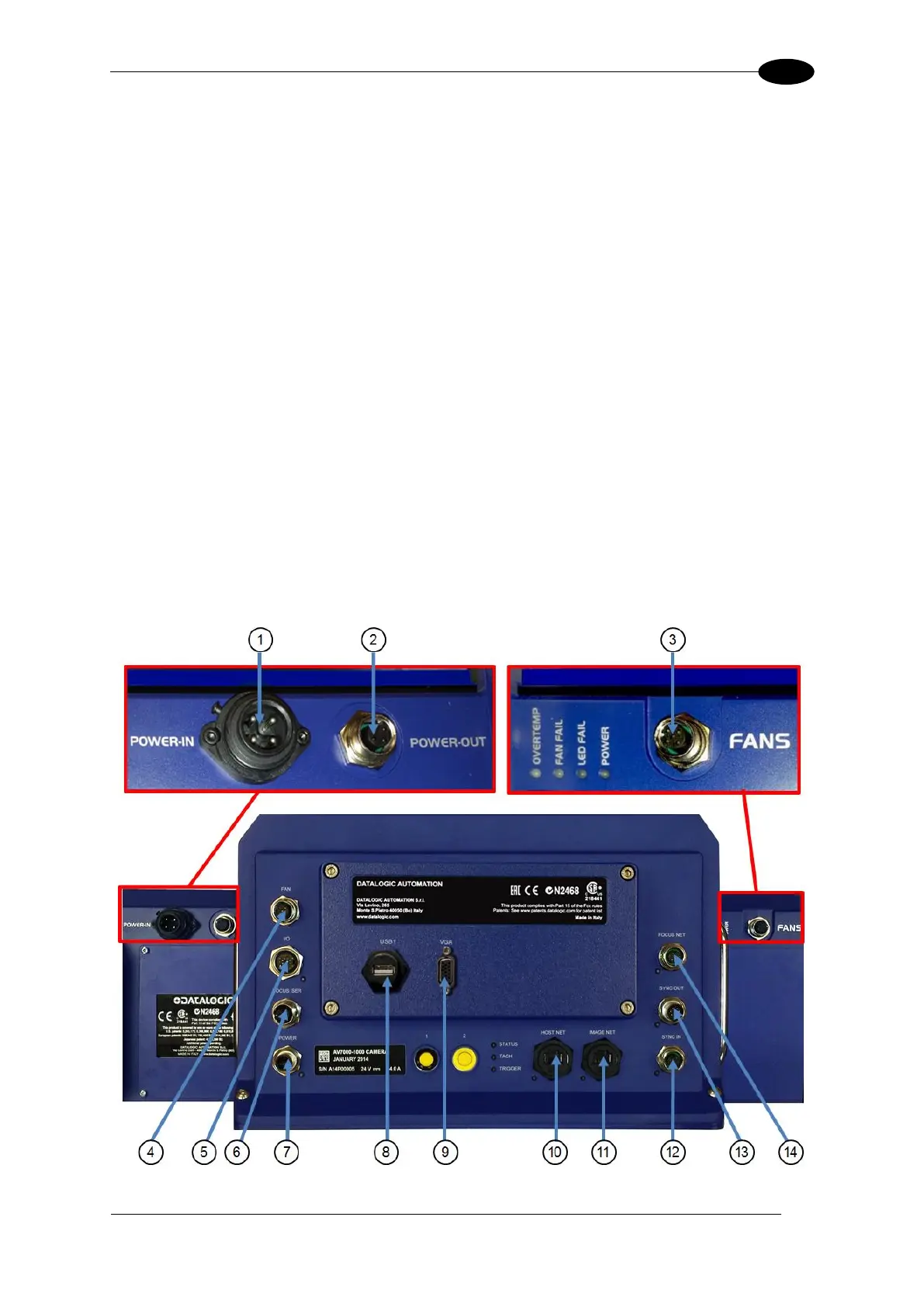
13. POWER IN – Main DC power connection for AV7000/AI7000 assembly
14. POWER OUT – Supplies DC power via cable to POWER connector on AV7000
15. FANS – Supplies DC power to AI7000 illumination fan units
AV7000 Camera
16. FAN – Supplies DC power to AV7000 fan unit
17. I/O – Provides connection to CBX Connection Box
18. FOCUS SER – Provides serial focus data to the camera ( ex. light curtain)
19. POWER – Connector receiving power from AI7000 POWER OUT
20. USB1 – OPTIONAL USB Keyboard and Mouse connection
21. VGA – OPTIONAL Monitor connector
22. HOST NET – Configuration and dimensioning data from the DM3610 if used
23. IMAGE NET – Configuration, Remote Monitor application, or image export
24. SYNC IN – AV7000 internal data, device network
25. SYNC OUT – AV7000 internal data, device network
26. FOCUS NET – Network focus data (RangeFinder)
Figure 57: AV7000/AI7000 Connector Panels

 Loading...

