AV7000 LINEAR CAMERA REFERENCE MANUAL
5.8 LED INDICATORS
5.8.1 AV7000 LEDs
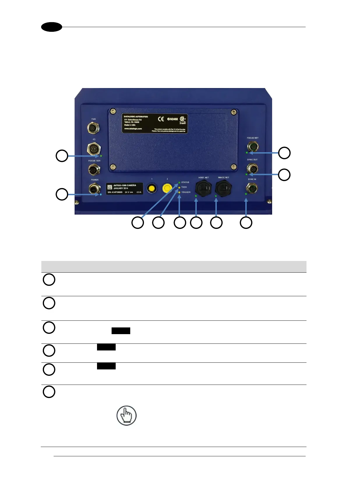
The AV7000 Camera has several LEDs on its back panels.
Figure 132: AV7000 LED Indicators
The indicators have the following meanings:
Solid Blue – Power LED indicating all internal power supplies are at the correct
voltage. Can be out if external power is supplied and an internal supply is out of
range.
Solid Green – Indicates CBX box connected has the ID+ to GND jumper and
this camera is the controller for the tunnel. The Tachometer/Encoder must be
connected to this unit.
Solid Green – Good status
Solid Yellow – active warning exists
Solid Red – active error exists
Yellow – Blinks with tachometer/encoder input
Yellow – Blinks on when Photoelectric Sensor is triggered
Green – Host Network Link at Gbit speed
Red – Host Network Data activity
NOTE: With a Gbit link, Green will always be
on and Red will blink, looking like it alternates
Green to amber. If connected to 100Mbit
network, the LED will only blink Red with
activity.

 Loading...

