DVP-15MC Series Motion Controller Operation Manual
4-6
*
1
:The output directions of the torque are illustrated as below when the value of X is 0 and 1 respectively.
Positive
direction
Negative
direction
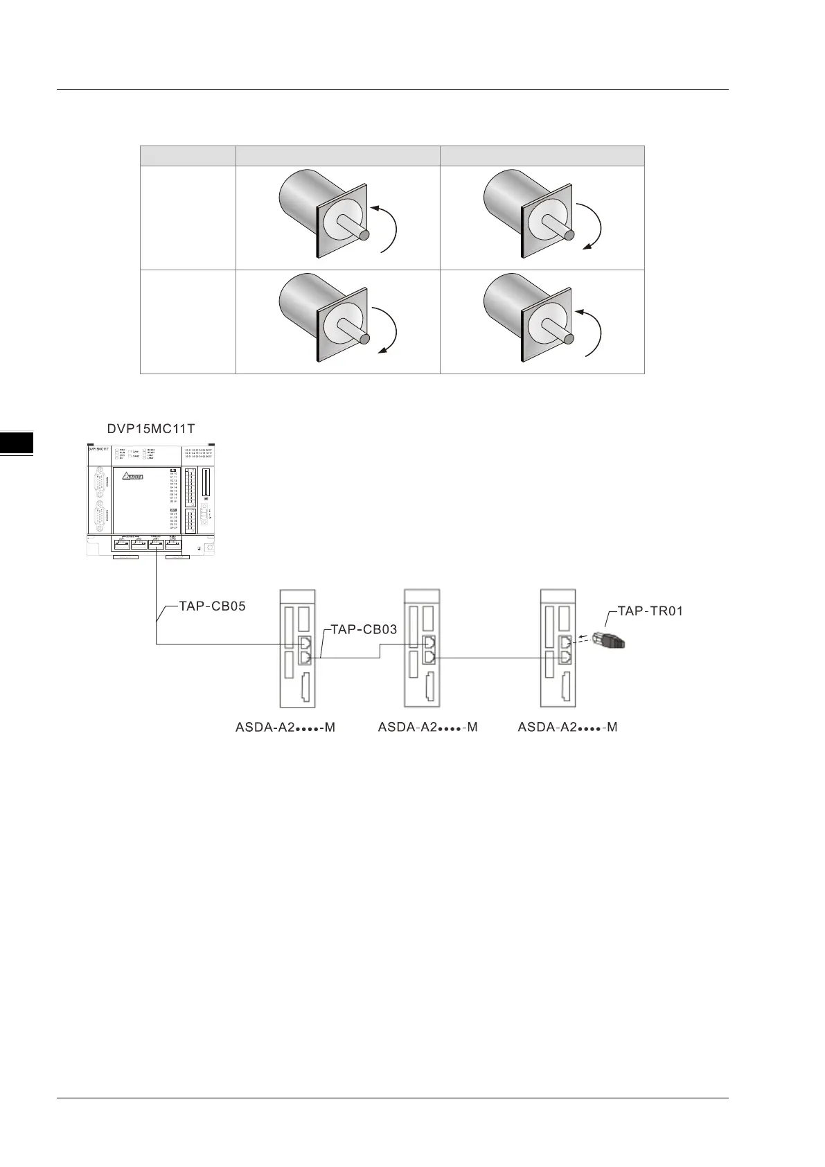
The wiring figure of the motion controller and ASDA-A2-XXXX-M-series servo drives
Notes:
1. Please refer to the servo user manual for the wiring of ASDA-A2-XXXX-M-series servo drives, servo
motors and encoders.
2. Choose UC-CMC003-01A or UC-CMC005-01A or UC-CMC010-01A communication cable according
to the field status.
3. There is one 120Ω terminal resistor embedded at Motion port. In the CANopen network consisting of
Motion port and servos, the other end of the network must be connected with a terminal resistor TAP-
TR01 which could be found in the packing box of the motion controller.

 Loading...


