Chapter 8 Logic Instructions
8-309
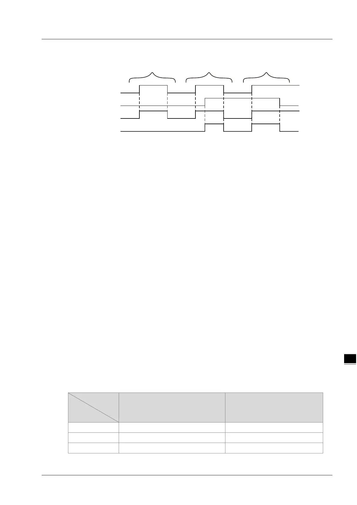
Output Update Timing Chart
Case 1: When Enable changes from FALSE to TRUE and Open is FALSE, Valid changes to TRUE and
LinkOpened is FALSE.
Case 2: In the situation that Enable changes from FALSE to TRUE and Valid changes to TRUE,
LinkOpened changes to TRUE as Open changes from FALSE to TRUE. Valid and LinkOpened
change to FALSE as Enable changes from TRUE to FALSE.
Case 3: When Open is TRUE and Enable changes from FALSE to TRUE, Valid and LinkOpened change
to TRUE. When Open changes to FALSE, LinkOpened changes to FALSE.
Function
1. The firmware of V1.11 major version and above as well as that of V1.04 minor version and above
support the instruction function.
2. When DVP04AD-SL and DVP04DA-SL modules are connected to the left side of DVP-50MC/15MC
series motion controller, the Left_Manage instruction can be used to enable or disable the function
of the left-side module device mapping. While Enable is TRUE, the function of the left-side module
device mapping is turned ON if Open is TRUE. The function of the left-side module device mapping
is turned OFF if Open is FALSE.
3. The function of the left-side module device mapping is disabled by default for one PLC. The function
of the left-side module device mapping can not be used until the Left_Manage instruction is re-
executed to enable the function after the function is enabled and the PLC is power ON again.
4. See the following input and output areas for the modules at different positions of the PLC when DVP-
50MC/15MC series PLC connects modules at its left side. The position of the first module at the left-
side of the PLC is 1 and the second one is 2 and so on. The positions of all modules at the left side
of the PLC can be counted in order.
No matter whether the device mapping function is enabled or not by the instruction, the calculation
method for the left-side module position is identical.
The mapping device area for AD modules is the input mapping area and the mapping device area
for DA modules is the output mapping area
Mapping
area
Position
Output mapping area Input mapping area
1 %MW6250~%MW6377 %MW6000~%MW6127
2 %MW6750~%MW6877 %MW6500~%MW6627
3 %MW7250~%MW7377 %MW7000~%MW7127
Enable
Open
Valid
LinkOpened
Case 1 Case 3
Case 2

 Loading...


