Chapter 8 Logic Instructions
8-323
FB
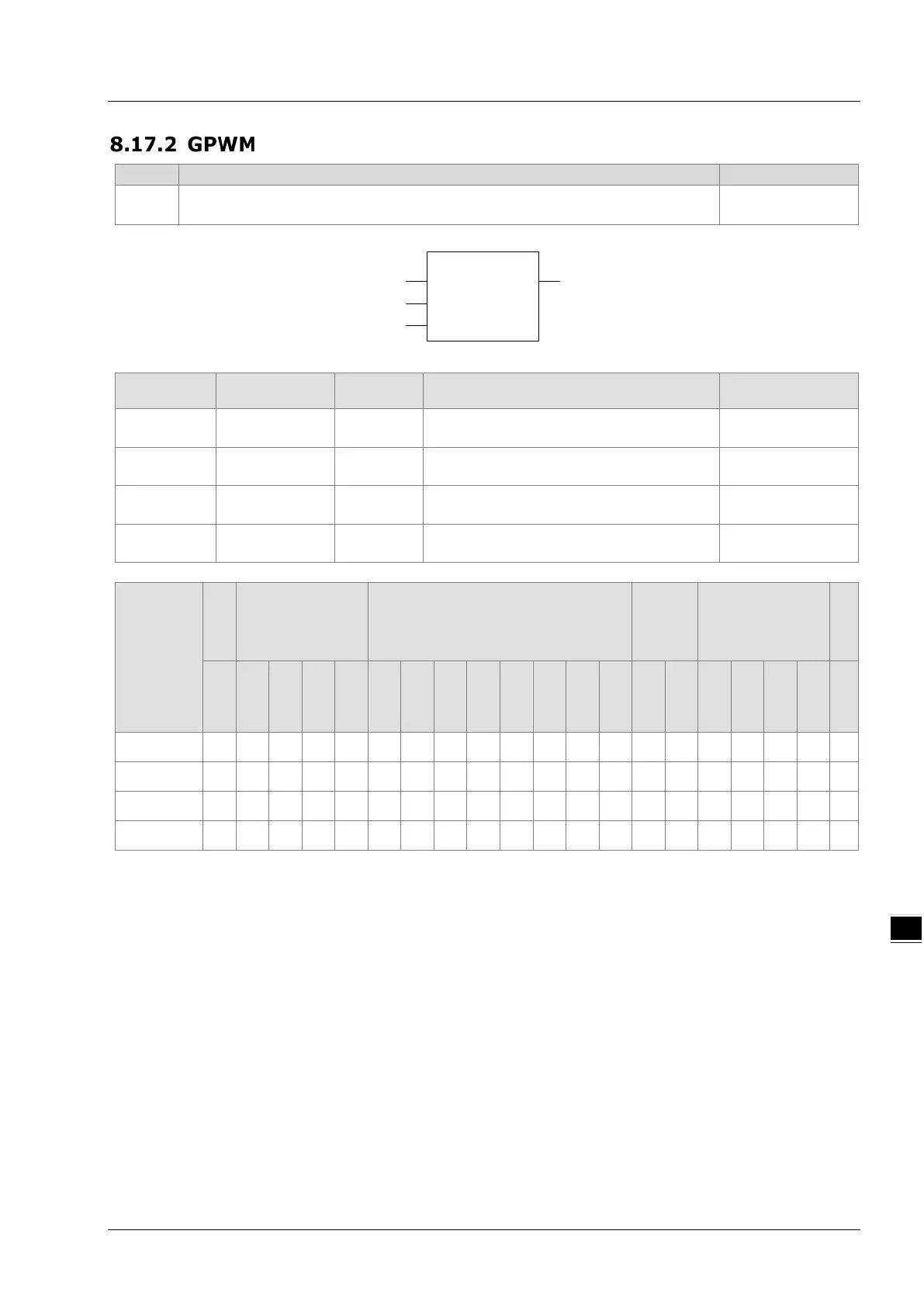
The GPWM instruction is used in the pulse output.
GPWM
Enable Out
GPWM instance_
In1
In2
Parameters
Meaning
Description Valid range
Enable Enable Input
The instruction execution starts when
Enable changes from FALSE to TRUE.
TRUE or FALSE
In1
The width of
output pulse
Input
When the instruction is executed, set the
width of output pulse (ms).
0~32767
In2
Input
When the instruction execution starts, set
the cycle of output pulse (ms).
1~32767
Out
outputing pulse
Output
The output is TRUE within the width of
output pulse.
TRUE or FALSE
Boolean
Bit string Integer
Real
number
Time, date
String
BOOL
BYTE
WORD
DWORD
LWORD
USINT
UINT
UDINT
ULINT
SINT
INT
DINT
LINT
REAL
LREAL
TIME
DATE
TOD
DT
STRING
Enable
●
In1
●
In2
●
Out
●
Note:
The symbol ● indicates that the parameter is allowed to connect to the variable or constant of the data
type.
Function Explanation
The GPWM instruction is used in the pulse output.
Please use GPWM instruction in the freewheeling task. Otherwise the output of GPWM instruction
may be inaccurate.
The values of In1 and In2 can be modified while GPWM instruction is being executed.
When In1 ≤ 0, the pulse output register has no output. When In1 ≥ in2, the pulse output register is
always ON.
The output of GPWM instruction can use a variable or any bit register. For details, refer to “Section
3.1.2 Registers and Data Types”.

 Loading...


