Chapter 11 Motion Control Instructions
11-133
Function Data type
is specified by TriggerInput.
The captured position is
converted from the number of
pulses that the external
encoder port of the controller
receives through axis
parameters.
Mode 2: The trigger signal comes from
the rising edge of the input
po
int of the servo drive. The
captured position is converted
from the number of pulses
which the servo motor feeds
back to the servo drive through
axis parameters.
Mode 3: The trigger signal comes from
the rising edg
point of the servo drive. T
he
captured position is converted
from the number of pulses that
CN1 port of the servo drive
receives through axis
parameters.
Mode 4: The trigger signal comes from
the rising edge of the
input
point of the servo drive. The
captured position is converted
f
rom the number of pulses that
CN5 port of the servo drive
receives through axis
parameters.
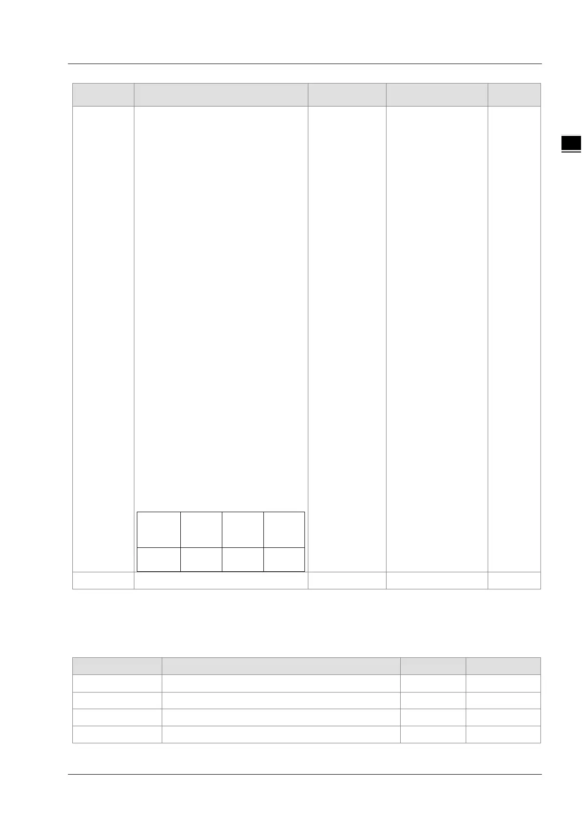
For the cyclical capture which is
conducted by using the input point of a
servo drive, different servo drive
models correspond to different input
points as shown in the table below.
drive
A2-M B3-M A3-M
DI7 DI3 DI7
Mask Reserved - - -
Notes:
1. In Mode 0 and mode 1, the same input point cannot be used for the position capture simultaneously.
2. In Mode 2, mode 3 and mode 4, the position capture cannot be performed for the same axis
simultaneously.
Output Parameters
Parameter name Function Data type Valid range
Valid TRUE when the captured value is valid. BOOL TRUE / FALSE
Busy TRUE when the instruction is being executed. BOOL TRUE / FALSE
Active TRUE when the axis is being controlled. BOOL TRUE / FALSE
CommandAborted
TRUE when the instruction is aborted.
BOOL TRUE / FALSE

 Loading...


