DVP-15MC Series Motion Controller Operation Manual
11-264
N_:The row number of G code in NC program
X_:Specify the terminal position of axis X, Unit: unit, data type: LREAL.
Y_:Specify the terminal position of axis Y, Unit: unit, data type: LREAL.
Z_:Specify the terminal position of axis Z, Unit: unit, data type: LREAL.
A_:Specify the terminal position of axis A, Unit: unit, data type: LREAL.
B_:Specify the terminal position of axis B, Unit: unit, data type: LREAL.
C_:Specify the terminal position of axis C, Unit: unit, data type: LREAL.
P_:Specify the terminal position of axis P, Unit: unit, data type: LREAL.
Q_:Specify the terminal position of axis Q, Unit: unit, data type: LREAL.
E_:Specify the acceleration and deceleration of the cutter. The positive number refers to the
acceleration; the negative number refers to the deceleration; unit: unit/second
2
; data type: LREAL.
F_:Specify the feed speed of the cutter, unit: unit/second, data type: LREAL.
When the cutter moves at a constant speed, the combined speed of all axes in G code is equal to F
value.
The method of calculation is shown as below.
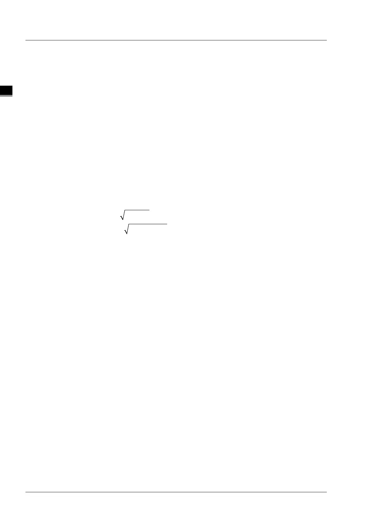
When two axes exist,
.
When three axes exist,
.
For more axes, F value could be calculated in the same way as above.
Instruction explanation:
1. G1 can control one or more axes and other axis can be omitted.
2. Both of E and F can be omitted.
If there is only one row of code in the CNC editing area and E, F are omitted, the velocity,
acceleration, deceleration and jerk are decided by the axis group parameters. They can be set
via DMC_SetG1Para. If there are multiple rows of codes and E and F in G1 code are omitted, the
velocity, acceleration, deceleration of the cutter are based on valid E and F in the previous rows
of codes. If the previous rows of G codes have not specified E and F, the axis group parameters
will prevail.
3. Absolute mode decided by G90: The terminal position of G1 is based on 0 unit.
4. Relative mode decided by G91: The terminal position of G1 is an incremental value beginning
from the current position.
Absolute mode example:
The initial positions of axis X, Y, Z are all 20000 units and their axis parameters are all default
values. The G codes to be executed are:
N0 G90
N1 G1 X50000 Y60000 Z70000
After G codes are executed, the Y/X curve for the whole movement process is shown below:

 Loading...


