DVP-15MC Series Motion Controller Operation Manual
A-10
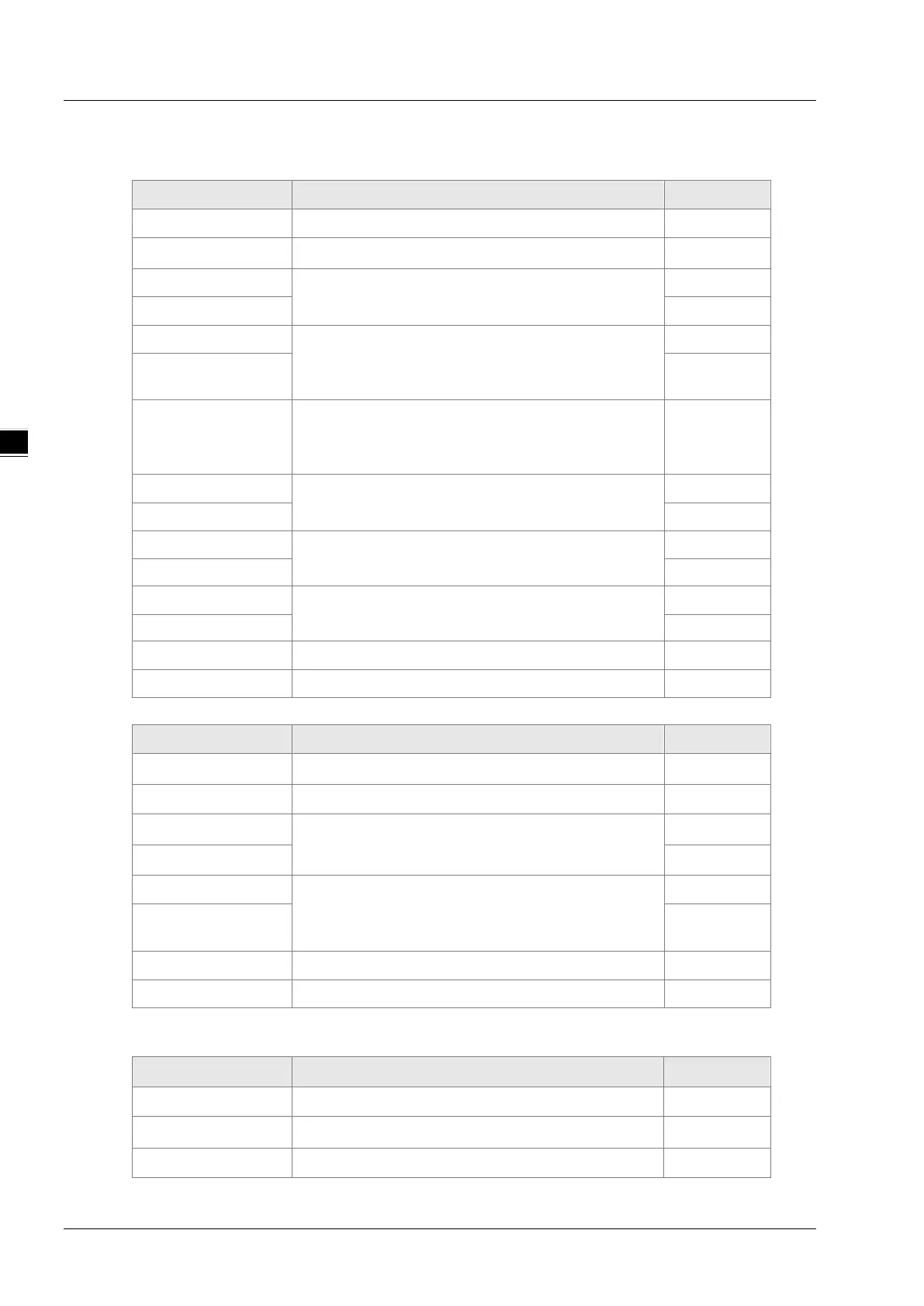
Function code 16#10 writes multiple word register values
Data structure of a request message:
Byte NO. Name Byte
Byte0
Modbus ID
Single byte
Byte1
Function code
Single byte
Byte2
The start address of controller’s word registers
where to write the value
High byte
Byte3 Low byte
Byte4
The number of addresses of controller’s word
registers where to write the value. (Counted by
word)
High byte
Byte5 Low byte
Byte6
The number of addresses of controller’s word
registers where to write the value. (Counted by
byte)
Single byte
Byte7
The address value written into controller’s word
register
High byte
Byte8 Low byte
…
The address value written into controller’s word
register
High byte
… Low byte
Byte n
The address value written into controller’s word
register
High byte
Byte n+1 Low byte
Byte n+2
Low byte of CRC check sum
Low byte
Byte n+3
High byte of CRC check sum
High byte
Data structure of a response message:
Byte NO. Name Byte
Byte0
Modbus ID
Single byte
Byte1
Function code
Single byte
Byte2
The start address of controller’s word registers
where to write the value
High byte
Byte3 Low byte
Byte4
The number of controller’s word registers where to
write the value.
(Counted by Word)
High byte
Byte5 Low byte
Byte6
Low byte of CRC check sum
Low byte
Byte7
High byte of CRC check sum
High byte
Data structure of an exception response message:
Byte NO. Name Byte
Byte0
Modbus ID
Single byte
Byte1
16#80+ function code
Single byte
Byte2
Exception response code
Single byte

 Loading...


