DVP-15MC Series Motion Controller Operation Manual
A-12
Note:
The value of Byte 2 in the response message is determined by the values of Byte 4 and
Byte 5 in the request message. For example, the number of the read bit registers in the
request message is A. Dividing A by 8 produces B. If the quotient is an integer, the number
of bytes of bit registers in the response message is B. Otherwise the number of bytes will
be B + 1.
See the example below for details.
Example
Read the state value of %QX2.0~%QX3.4 in DVP-15MC series motion controller via function
code 01. The address of %QX2.0 is 16#A010. Suppose the value of %QX2.0~%QX2.7 is 1000
0001 and %QX3.0~%QX3.4 is 1 0001.
Request message: 01 01 A0 10 00 0D DE 0A
Response message: 01 01 02 81 11 19 A0
Function code 16#02 reads multiple bit register values
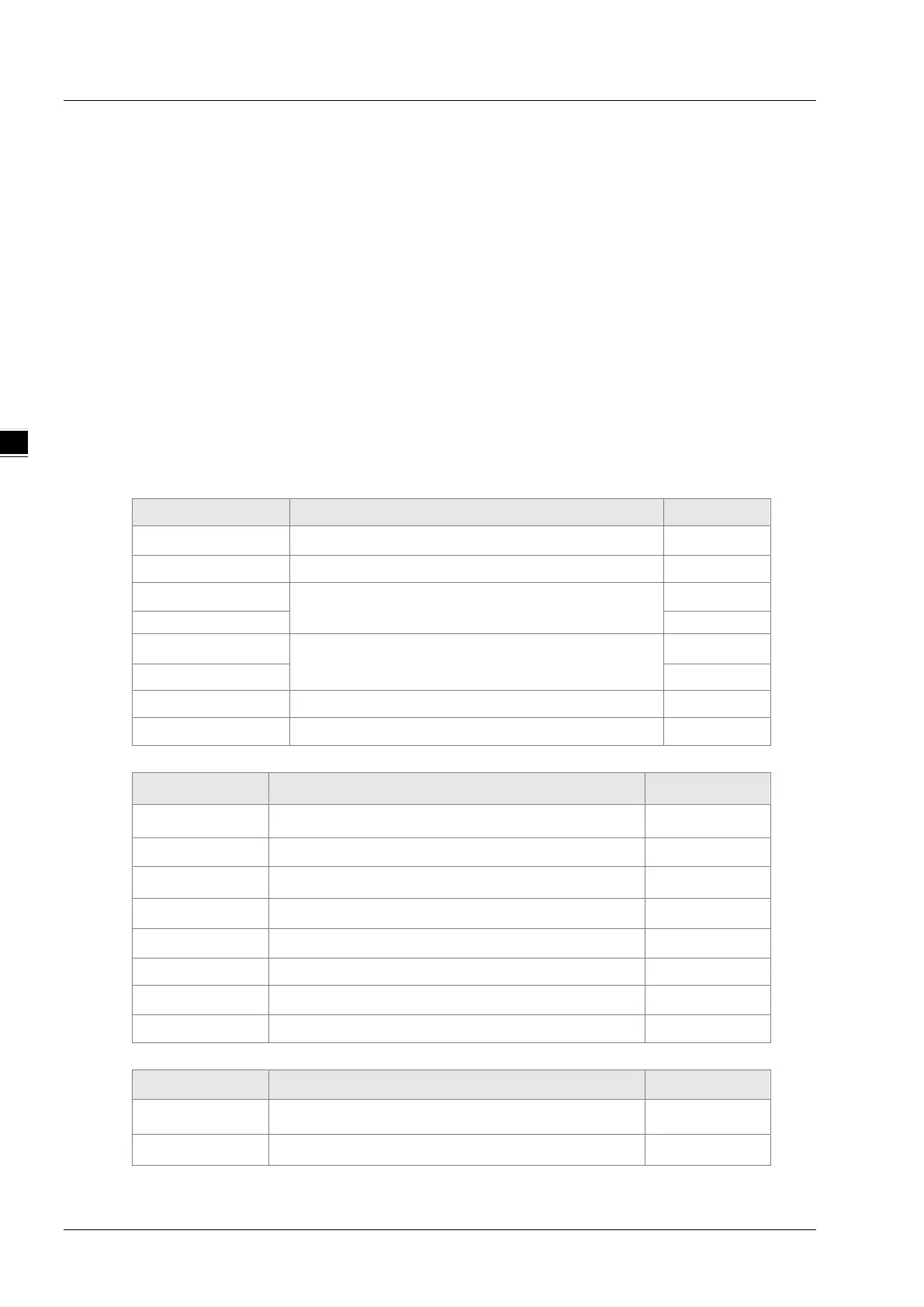
Data structure of a request message:
Byte NO. Name Byte
Byte0
Modbus ID
Single byte
Byte1
Function code
Single byte
Byte2
The start address of controller’s bit registers
where to read the state
High byte
Byte4
Read the number of bit registers.
High byte
Byte5 Low byte
Byte6
Low byte of CRC check sum
Low byte
Byte7
High byte of CRC check sum
High byte
Data structure of a response message:
Byte NO. Name Byte
Byte0
Modbus ID
Single byte
Byte1
Function code
Single byte
Byte2 Read the number of bytes of bit registers. Single byte
Byte3 Read the state value of the bit register. Single byte
… Read the state value of the bit register. Single byte
Byte n Read the state value of the bit register. Single byte
Byte n+1
Low byte of CRC check sum
Low byte
Byte n+2
High byte of CRC check sum
High byte
Data structure of an exception response message:
Byte NO. Name Byte
Byte0 Modbus ID Single byte
Byte1 16#80+ Function code Single byte

 Loading...


