Appendix B Modbus TCP Communication
B-7
B
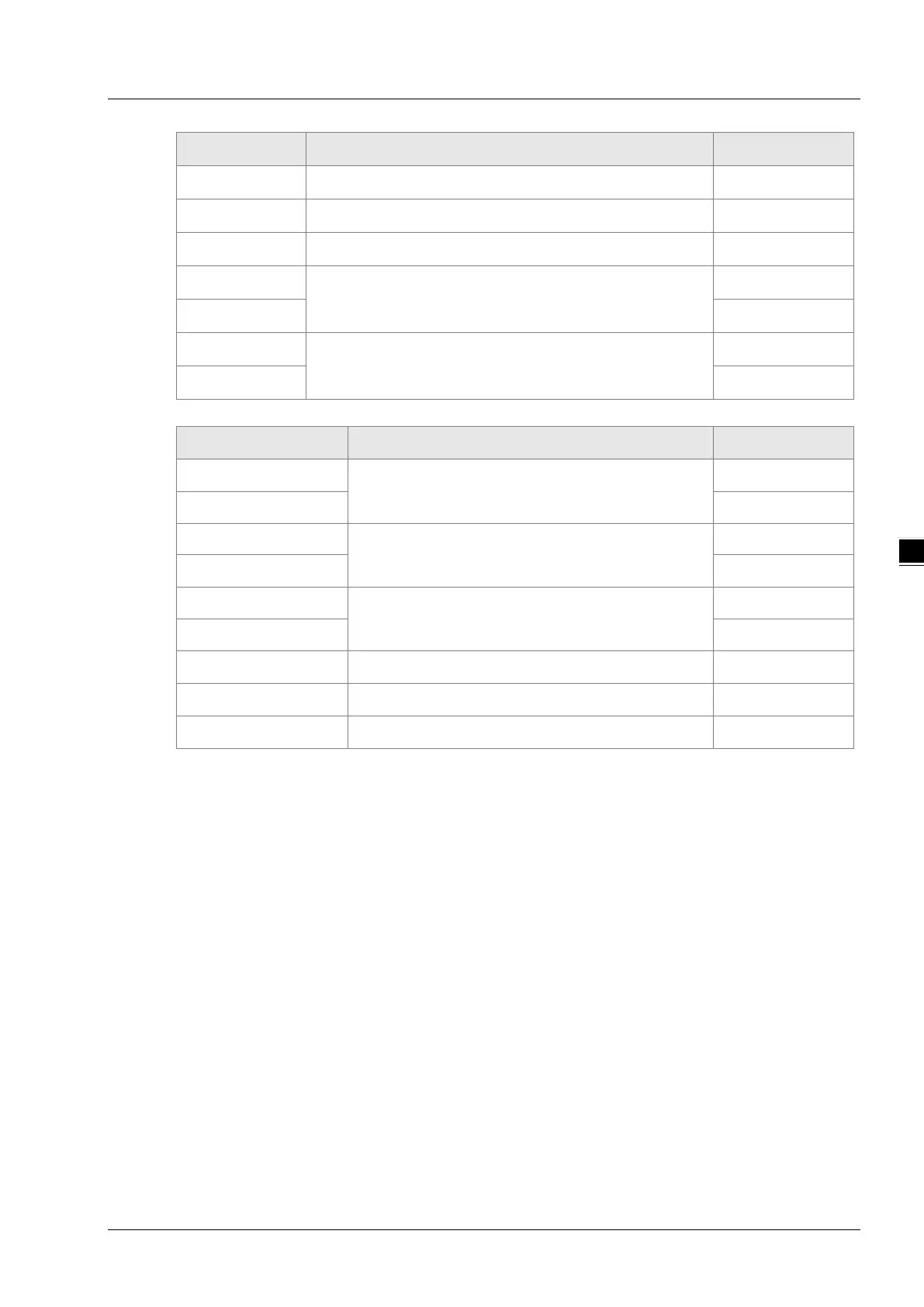
Byte NO. Name Byte
Byte5
Low byte
Byte6
Modbus ID Single byte
Byte7
Function code Single byte
Byte8
The start address of word registers where to write
values
High byte
Byte9
Low byte
Byte10
The number of word registers where to write values.
(Counted by Word)
High byte
Byte11
Low byte
Exception response message data structure:
Byte NO. Name Byte
Byte0
Transaction identifier
High byte
Byte1
Low byte
Byte2
Protocol identifier
High byte
Byte3
Low byte
Byte4
Modbus data length
High byte
Byte5
Low byte
Byte6
Modbus ID Single byte
Byte7
16#80+ function code Single byte
Byte8
Exception response code Single byte
Note:
How many bytes of data in a response message depend on the number of read register addresses
in DVP-15MC series motion controller in the request message. So the value of n in Byte n in the
response message can be calculated through reading the number of register addresses in DVP-
15MC series motion controller.
Example
To write 16#0100 and 16#0200 to the addresses 16#0000 and 16#0001 in DVP-15MC series
motion controller via function code 06.
16#0000 and 16#0001 are the Modbus addresses of %MW0 and %MW1 in DVP-15MC series
motion controller respectively.
Request message: 00 00 00 00 00 0B 01 10 00 00 00 02 04 01 00 02 00
Response message: 00 00 00 00 00 06 01 10 00 00 00 02

 Loading...


