Appendix B Modbus TCP Communication
B-9
B
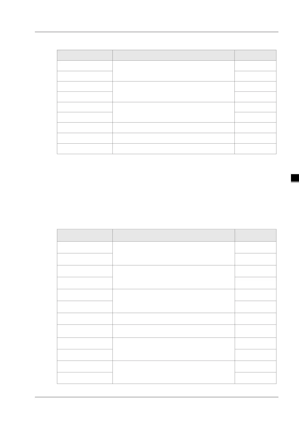
Exception response message data structure:
Byte NO. Name Byte
Byte0
Transaction identifier
High byte
Byte1
Low byte
Byte2
Protocol identifier
High byte
Byte3
Low byte
Byte4
Modbus data length
High byte
Byte5
Low byte
Byte6
Modbus ID Single byte
Byte7
16#80+ function code Single byte
Byte8
Exception response code Single byte
Example
To read the state value of %QX2.0~%QX3.4 in DVP-15MC series motion controller via function
code 02. 16#A010 is the address of %QX2.0. Suppose that %QX2.0~%QX2.7=1000 0001 and
%QX3.0~%QX3.4=10001.
Request message: 00 00 00 00 00 06 01 02 A0 10 00 0D
Response message: 00 00 00 00 00 06 01 02 02 81 11
Function code: 16#05 to write one single bit register value
Request message data structure:
Byte NO. Name Byte
Byte0
Transaction identifier
High byte
Byte1
Low byte
Byte2
Protocol identifier
High byte
Byte3
Low byte
Byte4
Modbus data length
High byte
Byte5
Low byte
Byte6
Modbus ID Single byte
Byte7
Function code Single byte
Byte8
Modbus address of a bit register
High byte
Byte9
Low byte
Byte10
The value written in the bit register
High byte
Byte11
Low byte

 Loading...


