DVP-15MC Series Motion Controller Operation Manual
B-12
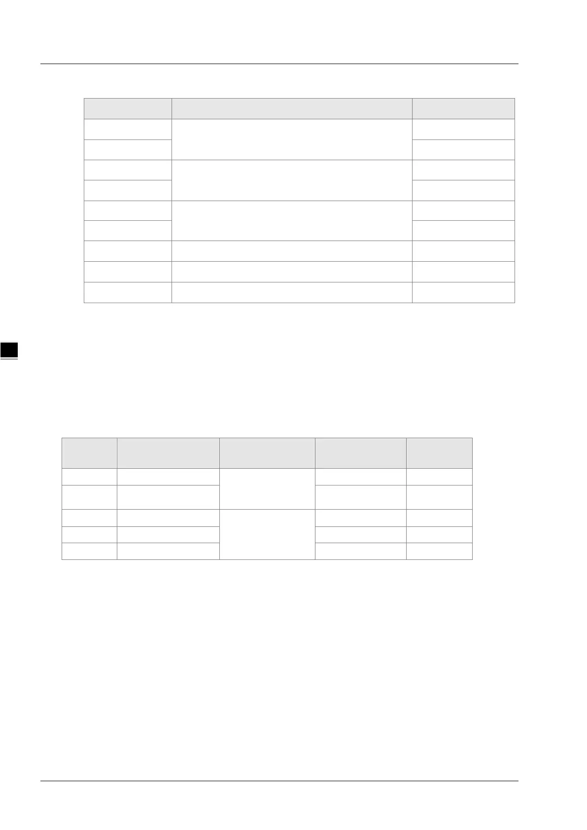
Exception response message data structure
Byte NO. Name Byte
Byte0
Transaction identifier
High byte
Byte1
Low byte
Byte2
Protocol identifier
High byte
Byte3
Low byte
Byte4
Modbus data length
High byte
Byte5
Low byte
Byte6
Modbus ID Single byte
Byte7
16#80+ function code Single byte
Byte8
Exception response code Single byte
Example
Set %QX0.0~%QX0.7=1000 0001 via function code 0F and set the address of %QX0.0 to
16#A000 in DVP-15MC series motion controller.
Request message: 00 00 00 00 00 0A 01 0F A0 00 00 08 01 81
Response message: 00 00 00 00 00 06 01 0F A0 00 00 08
B.5 Registers in DVP-15MC Series and Corresponding
Modbus Addresses
Register
name
Register no. Explanation Address (hex) Attribute
I %IX0.0~%IX127.7
Bit register
6000 ~ 63FF Read only
Q %QX0.0~%QX127.7 A000 ~ A3FF Read/write
I %IW0~%IW63
Word register
8000 ~ 803F Read only
Q %QW0~%QW63 A000 ~ A03F Read/write
M %MW0~%MW32767 0000 ~ 7FFF Read/write
 Loading...


