8
8.5 EXECUTION TIMING TABLES
In the following paragraphs, timing tables are presented that allow the calculation of best-
case, typical, and worst-case execution times for any FPCP instruction. These tables are
based on the assumptions previously stated and include the total execution time for each
instruction. In other words, the numbers that are calculated using these tables indicate the
time from the beginning of execution of the coprocessor instruction by the MPU (i.e., when
the instruction has been prefetched and loaded into the instruction decode register) to
completion of the instruction by the FPCP and for MPU (i.e., when a read of the response
CIR indicates a null (CA=0, PF=I), when conditional processing is completed, or when
the Fast operand transfer to or from the FPCP has been completed).
Bus cycle activity is also indicated by the tables and includes all bus cycles generated by
a particular operation. Note that instruction prefetch and operand write cycles requested
by the execution of a given instruction may not actually be executed during the excution
of the instruction, but are queued by the MPU bus interface unit for completion as soon
as the bus is available. (Refer to the MC68020 and MC68030 user's manual for more
information on bus cycle overlap.) When a floating-point operation is completed, a prefetch
request has been generated by the MPU to replace each word of the instruction stream
used by the instruction or to refill the instruction pipe in the case of a conditional branch,
a trap instruction, or an exception.
The timing information shown in the following tables for some operations includes three
numbers that depend on the context of the instruction (i.e., the alignment of the instruction
stream, whether the MPU instruction cache is enabled, and whether the cache contains
the instruction.)
1. The best-case value, where prefetches hit in the MPU on-chip cache and the instruction
benefits from the maximum overlap, in the MPU pipeline, with other instructions. Due
to the highly volatile nature of the instruction pipeline, this case is not easy to achieve
intentionally but occurs occasionally.
2. The cache-only case, where prefetches hit in the MPU on-chip cache, but the instruc-
tion does not overlap with preceding or following instructions.
3. The worst-case, where prefetches do not hit in the MPU on-chip cache or the cache
is disabled, and there is no instruction overlap. It is further assumed that the instruction
is aligned so that a prefetch is executed before the MPU writes to the FPCP command
CIR.
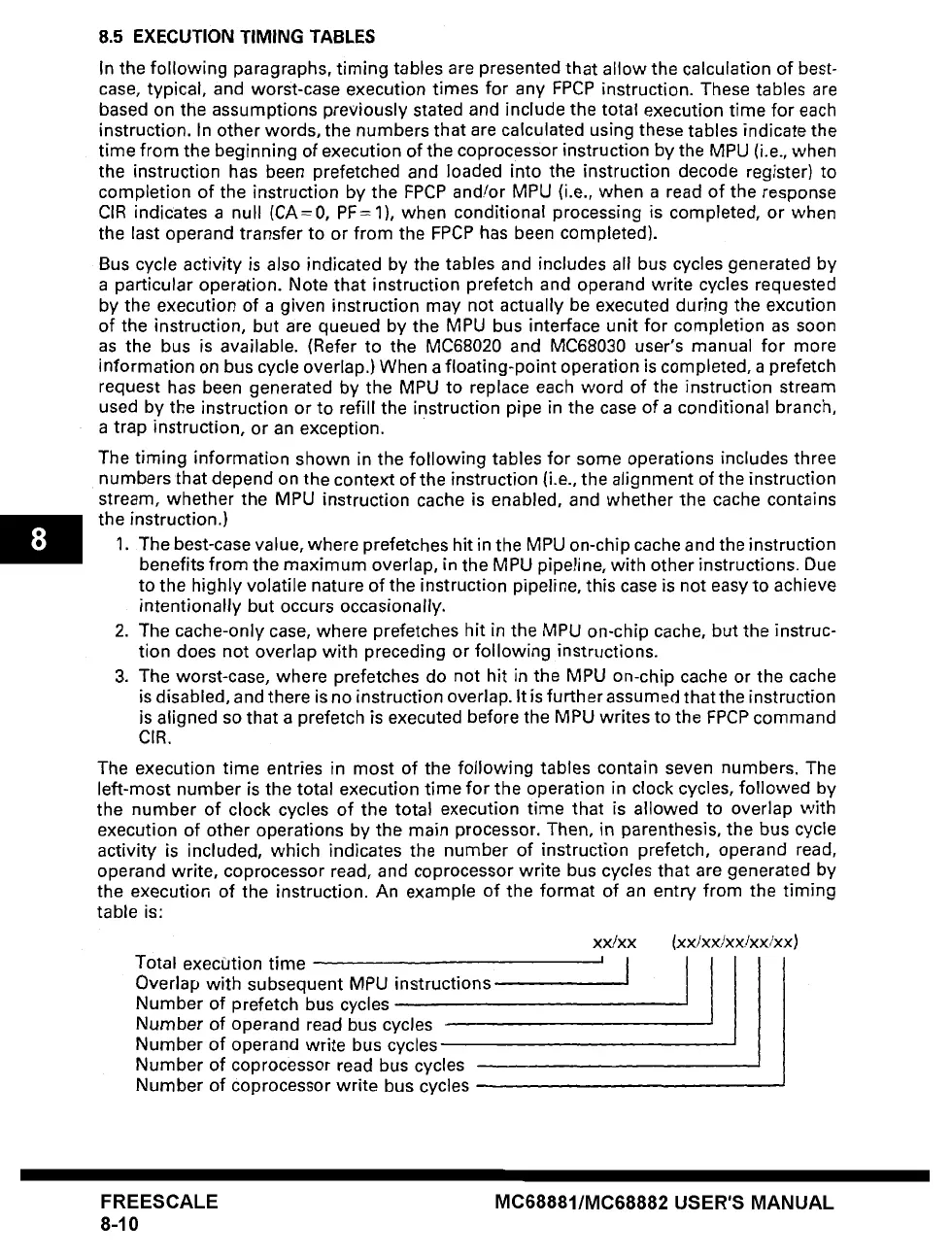
The execution time entries in most of the following tables contain seven numbers. The
left-most number is the total execution time for the operation in clock cycles, followed by
the number of clock cycles of the total execution time that is allowed to overlap with
execution of other operations by the main processor. Then, in parenthesis, the bus cycle
activity is included, which indicates the number of instruction prefetch, operand read,
operand write, coprocessor read, and coprocessor write bus cycles that are generated by
the execution of the instruction. An example of the format of an entry from the timing
table
is:
Total exec(Jtion time
Overlap with subsequent MPU instructions
Number of prefetch bus cycles
Number of operand read bus cycles
Number of operand write bus cycles
Number of coprocessor read bus cycles
Number of coprocessor write bus cycles
xx/xx
(xxJx×/xx/xxlxx)
'1 I
FREESCALE
8-10
MC68881/MC68882 USER'S MANUAL
 Loading...